Head maxillofacial bone implant and method for quickly molding same

A molding method and bone implantation technology, applied in the direction of bone implants, prostheses, medical science, etc., can solve the problems of displacement, troublesome postoperative complications, lack of technical and patent documents, etc., and achieve good tissue strength and Stability, avoidance of raw material waste, prevention of extrusion and irritation

Inactive Publication Date: 2015-04-01
卢清君
View PDF8 Cites 21 Cited by
  • Summary
  • Abstract
  • Description
  • Claims
  • Application Information

AI Technical Summary

Problems solved by technology

During the operation, the surgeon needs to process the prefabricated material on-site, such as bending, shaping, trimming, wound comparison, and re-trimming, when facing the wound of cranio-maxillofacial bone defect, which not only prolongs the exposure time of the wound , which increases the stimulation and damage to the wound soft tissue during the material shaping comparison process, and also increases the chance of infection during wound surgery, which may lead to damage such as prolonging the postoperative soft tissue repair time
At the same time, due to the difference in manual comparison and shaping, it is difficult to meet the requirements of perfect anatomical reduction, which limits the recovery of facial and orbital functions after surgery.
[0007] In addition, the discrepancy between the shape of the prefabricated material and the actual needs brings great troubles

Method used


Image

  • Head maxillofacial bone implant and method for quickly molding same
  • Head maxillofacial bone implant and method for quickly molding same
  • Head maxillofacial bone implant and method for quickly molding same

Examples


Embodiment 1

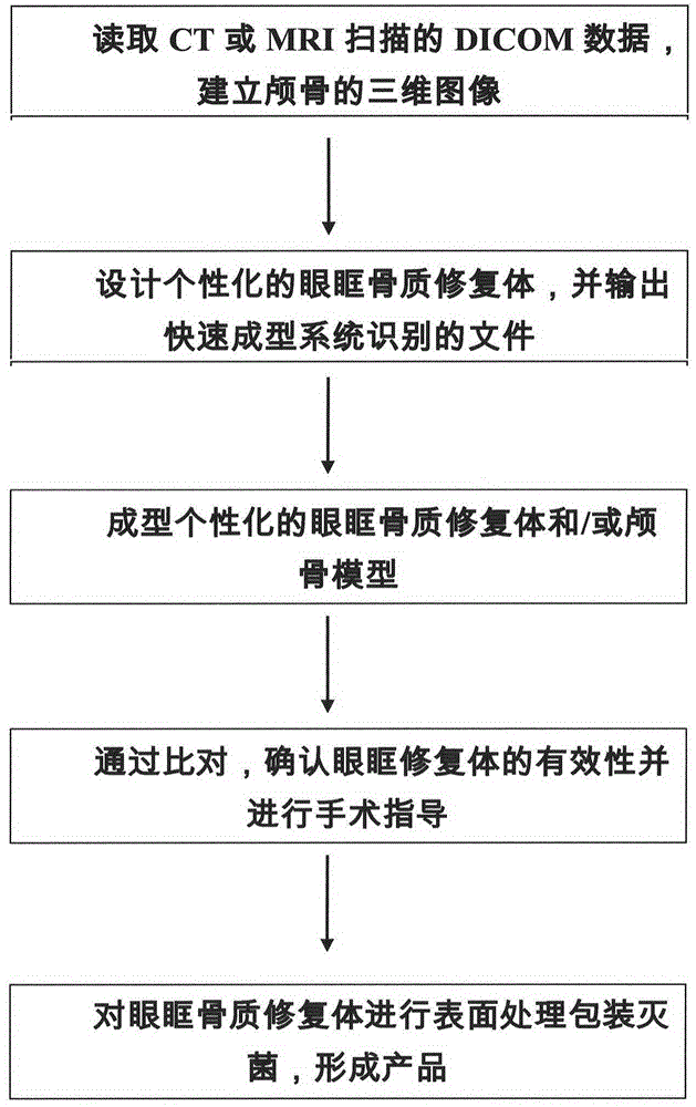
[0057] Research methods Such as figure 2 As shown, the main steps are as follows:

[0058] ① Using clinical DICOM files obtained from CT scans to reconstruct the three-dimensional skull picture picture.

[0059] ②Design a personalized bone defect restoration, and output the file recognized by the rapid prototyping system.

[0060] ③Personalized bone defect restoration and skull model with molding design.

[0061] ④ Through comparison, confirm the effectiveness of the bone defect restoration and provide surgical guidance.

[0062] The specific implementation process is described as follows:

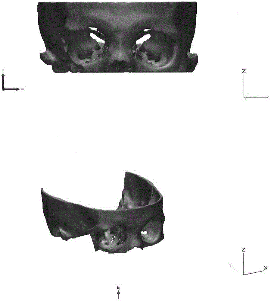
[0063] In the first step, the patient suffered a fracture of the left orbital wall due to various reasons and went to the doctor. The data files were obtained through CT scanning, and the patient's skull was reconstructed. Such as image 3 shown.

[0064] In the second step, through computer-aided design methods such as segmentation, mirroring, fusion, and surface reconstructio...


PUM


Abstract

The invention relates to a head maxillofacial bone implant and a method for quickly molding the same. The method is particularly a processing method for prosthesis for defects of the facial bones of human bodies, and the prosthesis is obtained by the aid of a processing technology for quickly polymerizing and molding powder. The method includes constructing maxillofacial post-traumatic models of patients according to image data of the bones of the patients; manufacturing three-dimensional models according to treatment repair requirements of clinical doctors by means of symmetric mirroring, curve design, database matching and the like. The image data of the bones of the patients are acquired by the aid of image diagnostic techniques such as CT (computed tomography) or MRI (magnetic resonance imaging). The three-dimensional models are matched with the traumatic positions of the patients. The head maxillofacial bone implant and the method have the advantages that the prosthesis models can be molded by the aid of the processing method for quickly molding the implant, and accordingly the prosthesis can be manufactured; the prosthesis which is processed in a personalized manner can be designed and processed for the patients with the maxillofacial defects and particularly patients with complicated defect structures, and the prosthesis with an anatomical repair effect and an effect of recovering functions of the maxillofacial organs of the patients can be manufactured.

Description

technical field [0001] The invention relates to the field of bone repair implants, in particular to a craniomaxillofacial bone implant used for craniofacial bone repair and a rapid prototyping method thereof. Background technique [0002] For bone repair implants, there is a skull implant in Patent Document 1 of a utility model in China, which specifically includes a skull prosthesis. The outer surface of the skull prosthesis is coated with a tantalum coating, that is, it is made of , Corrosion-resistant, wear-resistant, and metal tantalum with high bonding strength with the substrate is used as the coating material. [0003] In the whole skull, orbital wall fractures and bone defects are an important part, and they are also a common clinical disease in ophthalmology. The causes are often comminuted fractures caused by ocular trauma and traffic accidents, or after orbital tumor surgical resection. resulting in bone defects. Of course, craniofacial bone fractures and bone d...

Claims


Application Information

Patent Timeline
IPC IPC(8): A61F2/28A61L27/06
Inventor 卢清君梁新杰杨俊英宋维贤张敬学武珅刘谦
Owner 卢清君
Why Eureka
Try Eureka