Antenna impedance matching method on basis of key index data of power amplifier

A technology of power amplifier and key indicators, which is applied in the field of impedance matching debugging, can solve the problem that the circuit simulation software cannot be pre-installed, and achieve the effect of optimizing performance and improving calculation speed

Inactive Publication Date: 2015-04-01
重庆蓝岸科技股份有限公司
View PDF2 Cites 6 Cited by
  • Summary
  • Abstract
  • Description
  • Claims
  • Application Information

AI Technical Summary

Problems solved by technology

Also, circuit simulation software is unlikely to come pre-installed o

Method used


Image

  • Antenna impedance matching method on basis of key index data of power amplifier
  • Antenna impedance matching method on basis of key index data of power amplifier
  • Antenna impedance matching method on basis of key index data of power amplifier

Examples


Embodiment

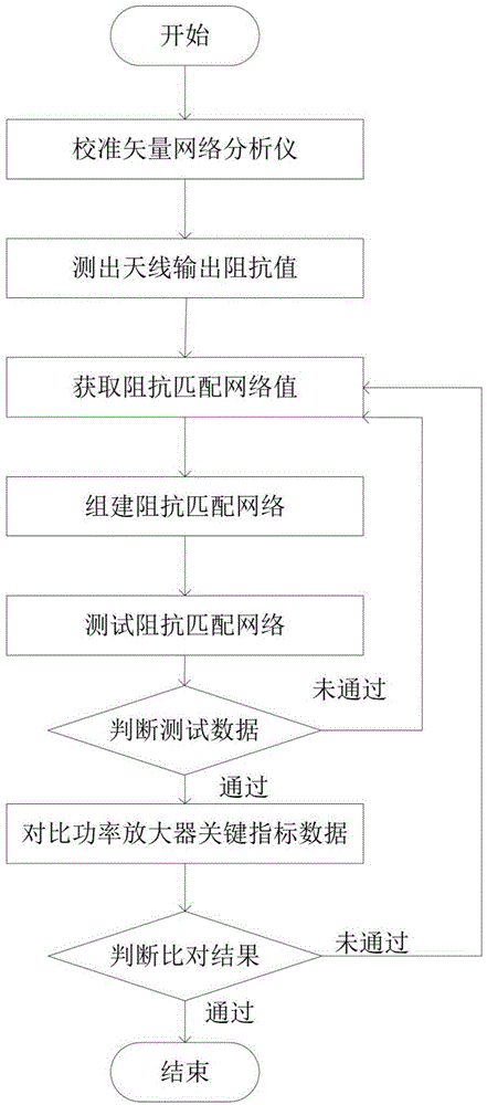
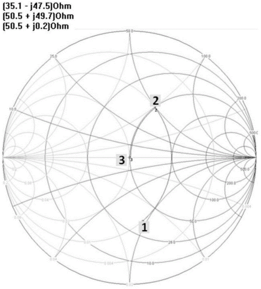
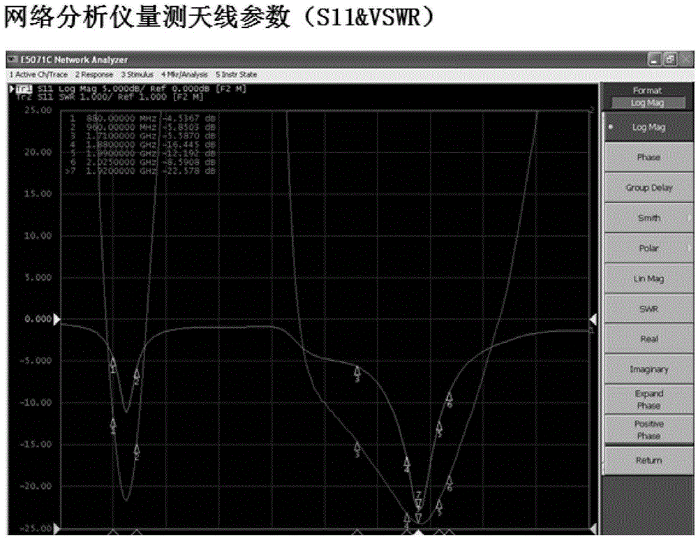
[0035] figure 2 It is the Smith circle diagram of the embodiment of the present invention, image 3 The vector network analyzer of the present embodiment measures the parameter diagram of the antenna, Figure 4 It is a data diagram of key indicators of a power amplifier according to an embodiment of the present invention. This embodiment design is under 824-849MHz PA working frequency, debugs according to the step of the present invention, the output impedance value of antenna is measured by vector network analyzer: Z=(35.1-J47.5) Ω, namely figure 2 At the position of point 1, the impedance network value is obtained through the Smith-Chart software. The result is that after the parallel inductance is 8.2nH, the antenna output impedance is Z=(50.5+J49.7)Ω, namely: figure 2 In the 2 o'clock position, after passing the verification, the VSWR is less than 3.5 and the reflection coefficient is less than -3dB in the frequency range of 400-1200. The output impedance value is Z=...


PUM


Abstract

The invention discloses an antenna impedance matching method on the basis of key index data of a power amplifier. The method mainly comprises the steps of calibrating a vector network analyzer; measuring output impedance value of an antenna; acquiring an impedance matching network value through Smith-Chart software; creating an impedance matching network; acquiring testing data of the created impedance matching network; verifying whether the testing data meet the index requirement; comparing the impedance matching network with the key index data of the power amplifier; determining whether the created impedance matching network reaches the optimal state; if not, debugging the impedance matching network; if so, passing the debugging. With the adoption of the antenna impedance matching method on the basis of the key index of the power amplifier, the accuracy can be ensured on the premise that an intuitive and physical conception is clear, thus the calculation speed is greatly raised, the performances of the antenna are optimized, and meanwhile, the shortages of computer simulation method and the manual calculation method are overcome, and as a result, the performances of the antenna are further optimized.

Description

technical field [0001] The invention relates to an impedance matching debugging method, in particular to an antenna impedance matching method based on key index data of a power amplifier. Background technique [0002] Impedance matching refers to a working state in which the load impedance and the internal impedance of the signal source are adapted to each other to obtain the maximum power output. There are many methods for impedance matching debugging, but each has its own disadvantages. For example: computer simulation method and manual calculation method. Software such as computer simulation is complicated to use because it is designed for different functions than just impedance matching. Designers must be familiar with inputting a large amount of data in the correct format, and designers also need to have the skills to find useful data from a large number of output results. Also, circuit simulation software is unlikely to come pre-installed on a computer unless the co...

Claims


Application Information

Patent Timeline
IPC IPC(8): H03F1/56
Inventor 张雷
Owner 重庆蓝岸科技股份有限公司
Why Eureka
Try Eureka