Magnesium stabilized ultra low soda cracking catalysts
A catalyst, catalytic cracking technology, applied in physical/chemical process catalysts, molecular sieve catalysts, catalyst activation/preparation, etc., can solve problems such as reducing catalytic activity, stability and yield, affecting bottom-line profit generation, reducing catalyst performance, etc. Achieve activity and hydrothermal stability, good coke and hydrogen selectivity, improved FCC process
- Summary
- Abstract
- Description
- Claims
- Application Information
AI Technical Summary
Problems solved by technology
Method used
Image

Examples
example 1
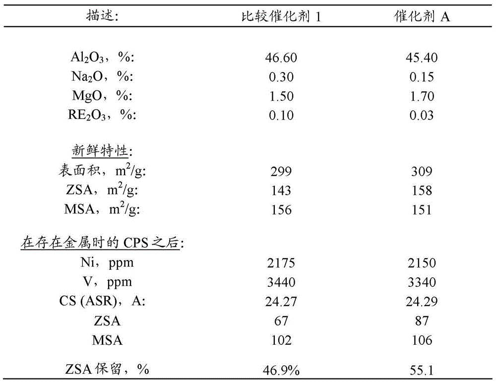
[0070] Example 1: Ultra-low Na with 1.6% MgO 2 O catalyst
[0071] with containing 0.9 wt% Na 2 Catalyst A was prepared from the USY zeolite of O. will contain 25% USY zeolite (0.9% Na 2 O), a slurry of 20% colloidal silica (Bindzil), 35% acid peptized alumina and 20% clay was ground in a Drais mill and subsequently spray dried in a Bowen spray dryer. The spray-dried catalyst was calcined at 400 °C for 40 minutes in a laboratory muffle furnace. Washing the calcined catalyst to remove Na 2 O. After the washing step, with enough MgSO 4 The solution impregnated the filter cake to form 1.6 wt% MgO on the catalyst. The resulting catalyst was designated Catalyst A. Catalyst A contains 0.15 wt% Na 2 O, which corresponds to 0.60 wt% Na based on zeolite 2 O. The characteristics of the catalyst are shown in Table 1 below.
example 2
[0077] Example 2: DCR Evaluation of Catalyst A
[0078] Using the cyclopropene steam (CPS) protocol (see ACS Symposium Series by Lori T. Boock, Thomas F. Petti and John A. Rudesill, 634, 1996, 171-183 (ACS Symposium Series, Vol. 634, 1996 , pp. 171-183)) deactivates Catalyst A and Comparative Catalyst 1. The catalyst was deactivated in the presence of 2000ppm Ni / 3000ppm V. After deactivation, the physical and chemical properties of Catalyst A and Comparative Example 1 are listed in Table 1 above.
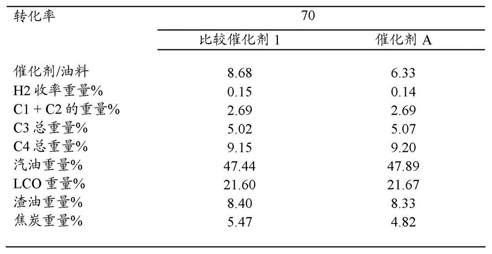
[0079] Catalyst A exhibited significantly better retention of zeolite surface area (ZSA) after deactivation than Comparative Catalyst 1 . The deactivated catalyst was then run through a Davison Circulation Riser (DCR) unit with resid feed. The reactor temperature was 527°C. The DCR test results are reported in Table 2 below.
[0080] Table 2
[0081] Ultra-low sodium Mg-containing catalyst B after CPS in the presence of 2000ppm Ni / 3000ppm V The interpolated DCR yield o...
example 3
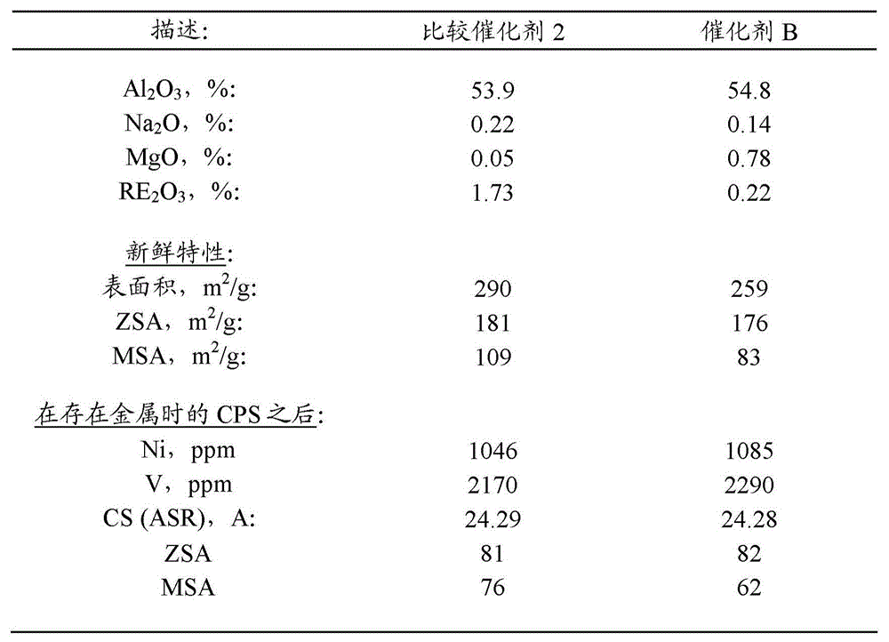
[0084] Example 3: Ultra-low Na with 0.8% MgO 2 O catalyst
[0085] with containing 0.9% Na 2 Catalyst B was prepared from the USY zeolite of O. A slurry comprising 25% USY zeolite, 15% boehmite alumina, 18% aluminum chlorohydrate and 42% clay was ground in a Drais mill and then spray dried in a Bowen spray dryer. The spray-dried catalyst was calcined at 400 °C for 40 minutes in a laboratory muffle furnace. Washing the calcined catalyst to remove Na2 O. After the washing step, with enough MgSO 4 The solution impregnated the filter cake to form 0.8 wt% MgO on the catalyst. The resulting catalyst was designated Catalyst B. Catalyst B contains 0.14 wt% Na 2 O, which corresponds to 0.56 wt% Na based on zeolite 2 O. The characteristics of the catalyst are shown in Table 3 below.
PUM
| Property | Measurement | Unit |
|---|---|---|
| particle size | aaaaa | aaaaa |
| particle size | aaaaa | aaaaa |
| particle size | aaaaa | aaaaa |
Abstract
Description
Claims
Application Information
PatSnap Eureka turns technology decisions into work you can execute. Powered by our Innovation Knowledge Graph, it runs expert workflows across engineering, life sciences, materials and intellectual property. Get your review-ready output in minutes.


