Optical microwave waste gas purifier

A waste gas purifier and purifier technology, applied in the direction of chemical instruments and methods, dispersed particle separation, separation methods, etc., can solve the problems of increasing atmospheric precipitation, plant leaf damage, plant yield decline, etc., to achieve low operating costs, The effect of short process flow and low investment intensity

Inactive Publication Date: 2015-04-08
SUZHOU BOHAN ENVIRONMENTAL PROTECTION TECH
View PDF2 Cites 0 Cited by
  • Summary
  • Abstract
  • Description
  • Claims
  • Application Information

AI Technical Summary

Problems solved by technology

The harm of air pollutants to the human body is multifaceted, mainly manifested in respiratory diseases and physiological dysfunction, and diseases caused by stimulation of mucous membrane tissues such as eyes and noses; the harm to plants, when the concentration of pollutants is high, it will affect plants. Acute damage will cause scars on the surface of plant leaves, or the leaves will wither and fall off; when the concentration of pollutants is not high, it will cause chronic damage to plants, causing the leaves of plants to chlorotic, or the symptoms of harm cannot be seen on the surface. However, the physiological functions of plants have been affected, resulting in a decline in plant yield and deterioration of quality; the impact on weather and weather is mainly manifested in: reducing the amount of solar radiation reaching the ground, increasing atmospheric precipitation, acid rain, and increasing atmospheric temperature; therefore In order to protect the environment, exhaust gas must be treated well, and there are many existing exhaust gas treatment methods, which have limitations in application range and application fields, and cannot be widely used in various fields, and these exhaust gas treatment methods The method can't deal with the waste gas well and thoroughly

Method used


Image

  • Optical microwave waste gas purifier

Examples


Embodiment Construction

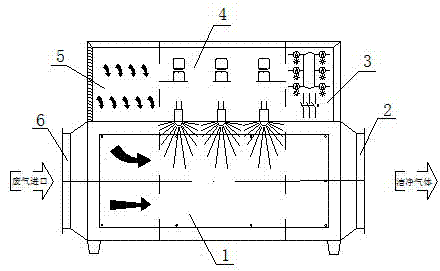
[0011] Such as figure 1 An optical microwave exhaust gas purifier shown includes a purifier body 1. The left end of the purifier body 1 is an exhaust gas inlet 6 and the right end is a clean gas outlet 2. The upper right end of the purifier body 1 is provided with a control system panel 3 The middle of the purifier body 1 is provided with a microwave emission system 4; the upper left end of the purifier body 1 is provided with an air chamber 5 for introducing air into the purifier body 1; the air chamber 5 An air filter is connected to it; an exhaust gas filter is arranged in the purifier body 1.

[0012] The main principle of optical microwave processing is that an electromagnetic wave is generated by microwave, and the heating property of electromagnetic wave is used. As an electromagnetic wave, it also has wave-particle duality. Its interaction with biological tissues is mainly manifested in thermal and non-thermal effects.

[0013] Electromagnetic waves can be transmitted in...


PUM


Abstract

The invention relates to an optical microwave waste gas purifier which comprises a purifier body, wherein a waste gas inlet is formed in the left end of the purifier body; a clean gas outlet is formed in the right end of the purifier body; a control system panel is arranged at the upper part of the right end of the purifier body; a microwave emitting system is arranged at the upper middle part of the purifier body. Compared with the traditional waste gas treatment method, the optical microwave waste gas treatment method has the advantages that the unit investment strength for waste gas treatment low, the occupied area is small, a large-scale waste gas treatment project or small-scale dispersed waste gas treatment projects can be built, the waste gas treatment process flow is short, physico-chemical degradation reaction of pollutants in waste gas is fast, the comprehensive energy consumption of unit waste gas treatment is low, the operation cost of unit waste gas treatment is low, and the waste gas treatment process is free from the influence of environmental temperature and the concentration of original waste gas pollutants.

Description

Technical field [0001] The invention relates to an exhaust gas purifier in the environmental protection industry, in particular to an optical microwave exhaust gas purifier. Background technique [0002] At present, the main air pollution is the fuel in the factory area. Various pollutant gases produced during combustion and production processes are discharged into the air. The main air pollutants in China include: sulfur dioxide, smoke, industrial dust and nitrogen oxides. The harm of air pollutants to the human body is multifaceted. The main manifestations are respiratory diseases and physiological dysfunctions, as well as mucosal tissues such as eyes and noses that are irritated and diseased; the harm to plants, when the pollutant concentration is high, it will affect plants. Acute hazards, causing spots on the surface of plant leaves, or desirably causing leaves to wither and fall off; when the concentration of pollutants is not high, it will cause chronic hazards to plants, ...

Claims


Application Information

Patent Timeline
Patent Type & Authority Applications(China)
IPC IPC(8): B01D53/76
Inventor 陈道斌
Owner SUZHOU BOHAN ENVIRONMENTAL PROTECTION TECH
Why Eureka
Try Eureka