
Suitable for fluid connection buildings with rapid bends

A technology for buildings and curves, which is applied in the direction of construction, artificial waterways, river regulation, etc. It can solve problems such as unfavorable flow patterns, diamond-shaped shock waves, and continuous folding, so as to reduce the probability of damage and avoid impact and abrasion damage. Effect

Inactive Publication Date: 2016-01-27
SICHUAN UNIV
View PDF5 Cites 0 Cited by
  • Summary
  • Abstract
  • Description
  • Claims
  • Application Information

AI Technical Summary

Problems solved by technology

[0006] Aiming at the current technical situation and deficiencies of the current state of the building in which the flow state of the torrent bend is connected, the purpose of the present invention is to propose a hydraulic structure that can make the flow state of the torrent water flow smoothly transition in the bend with a large turning angle. In order to solve the problem of unfavorable flow conditions such as diamond-shaped shock waves and continuous folding caused by the rapid flow of the curve in the downstream chute of the curve
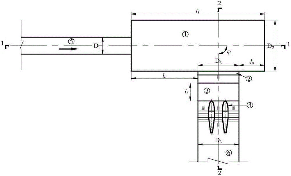
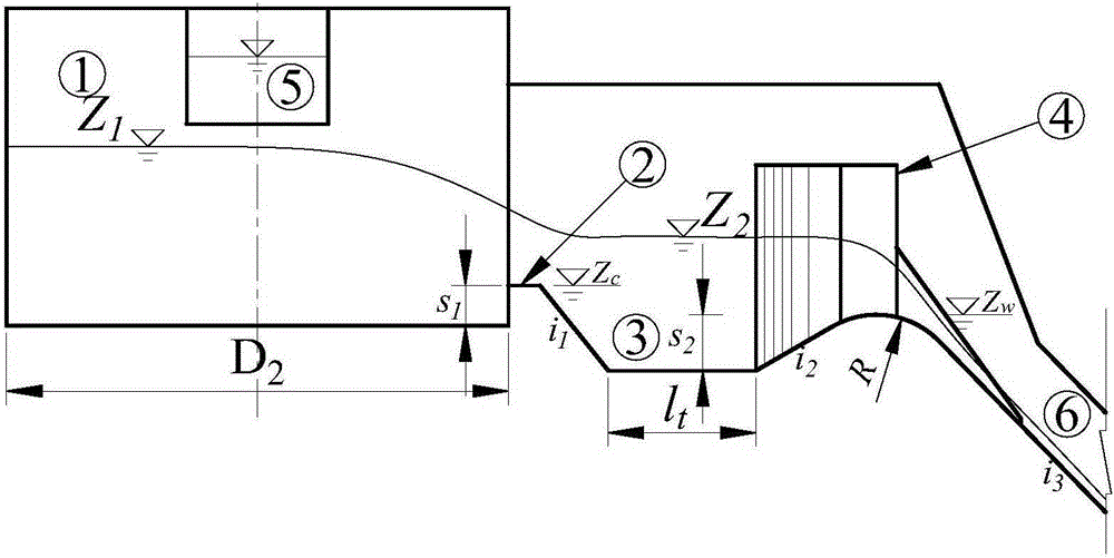
The basic solution of the present invention is to adopt the arrangement form of falling flow stilling pool + side weir + flow state regulating pool + rectifying tail pier at the rapids bend, so as to solve the problem of diamond-shaped shock waves and continuous folding of the water flow in the downstream chute of the bend. and other unfavorable flow problems

Method used


Image

  • Suitable for fluid connection buildings with rapid bends
  • Suitable for fluid connection buildings with rapid bends
  • Suitable for fluid connection buildings with rapid bends

Examples


Embodiment Construction

[0040] The implementation examples of the present invention are given below in conjunction with the accompanying drawings, and the present invention will be further described through the examples. It is necessary to specify here that the specific implementation of the present invention is not limited to the forms in the examples. According to the disclosed content of the present invention, those skilled in the art can also implement in other specific ways. Therefore, the examples It should not be understood as a specific embodiment that the present invention can only implement.

[0041] Engineering example

[0042] The example of this project is the flood drainage system of a construction stockyard of a hydropower station. It is built in a debris flow ditch. During the flood season, the water volume is large and the sand content is large. The peak flow rate of the 50-year flood in the ditch is 192m 3 / s, the 100-year flood peak discharge is 219m 3 / s. The flood drainage sys...


PUM


Abstract

The invention discloses a flow state connected building suitable for a supercritical flow bend. Incoming flow from the upstream of the bend enters a stilling pool of the flow state connected building in a single-stage fall mode; a side weir is arranged on the side wall of the stilling pool and is connected with a downstream flow state regulating tank; a rectifying tail pier is arranged at an outlet of the flow state regulating tank; the axis of the rectifying tail pier is in parallel to that of a flow passage on the downstream of the bend. Design of the flow connected building adopts the main principle that firstly, the energy dissipation effect of the stilling pool is utilized to reduce a flow rate of the incoming flow, and local subcritical flow is formed in the stilling pool; then the principle that the low flow rate has high adaptability to an overflowing boundary is utilized, the side weir is adopted to change the flow direction of water flow, and by the flow state regulating tank, the flow rate of the water flow is further reduced and the flow state is further improved; finally, the rectifying tail pier is utilized to regulate the flow direction to be in parallel to the axis direction of the flow passage on the downstream of the bend. According to the flow state connected building suitable for the supercritical flow bend, the adverse flow states, such as rhombus waves, a large water surface transverse slope and a deflected side wall, formed by the water flow in the supercritical flow bend can be effectively avoided, and washout and erosion damage and the like of water flow with high sand content on the boundary of the flow passage on the downstream of the bend are reduced and avoided.

Description

technical field [0001] The present invention relates to flood discharge or water conveyance structures in water conservancy and hydropower projects or disaster prevention and reduction projects, more specifically, relates to flood discharge or water conveyance structures with relatively large turning angles and rapid flow. Background technique [0002] Flood discharge structures in water conservancy and hydropower projects and flood discharge and water delivery structures in water treatment projects are affected by terrain, geological and other constraints, and there may be rapid bends with large turning angles. For the torrent water flow, due to the combined effect of the inertia of the water body and the centrifugal force of the bend, the adaptability to the flow boundary is poor, and it is difficult for the torrent water body to achieve a smooth connection in the bend. The main performance is that the water flow in the bend will hit the outside of the building The side wa...

Claims


Application Information

Patent Timeline
Patent Type & Authority Patents(China)
IPC IPC(8): E02B3/02E02B5/08E02B8/06
CPCE02B3/00E02B5/00Y02A10/30
Inventor 马旭东聂锐华邓军刘兴年雷明慧
Owner SICHUAN UNIV
Learn More