Non-load starting device and method for variable hydraulic pump

A variable hydraulic pump, no-load start-up technology, applied in the direction of fluid pressure actuation device, fluid pressure actuation system safety, servo meter circuit, etc., can solve the hydraulic system pressure shock, hydraulic pump, hydraulic system and working device damage, The size and volume of the unloading device increase, so as to achieve the effects of small impact on the hydraulic system, small starting torque and simple structure

Inactive Publication Date: 2015-04-22
BEIJING INSTITUTE OF TECHNOLOGYGY
View PDF6 Cites 9 Cited by
  • Summary
  • Abstract
  • Description
  • Claims
  • Application Information

AI Technical Summary

Problems solved by technology

Usually, the no-load start of the hydraulic pump is: when starting, the output oil of the hydraulic pump directly flows back to the oil tank through the action of hydraulic components such as electromagnetic overflow valve, electromagnetic directional valve, and electro-hydraulic directional valve, and the output oil hydraulic pressure The force is close to zero, that is, the hydraulic pump is working in an unloaded state, but when the flow rate of the hydraulic pump output oil is relatively large and the diameter of the hydraulic component that plays the role of unloading is small, the oil output by the hydraulic pump is under pressure. In this way, there will be power loss on the unloaded hydraulic components;

Method used


Image

  • Non-load starting device and method for variable hydraulic pump
  • Non-load starting device and method for variable hydraulic pump
  • Non-load starting device and method for variable hydraulic pump

Examples


Embodiment 1

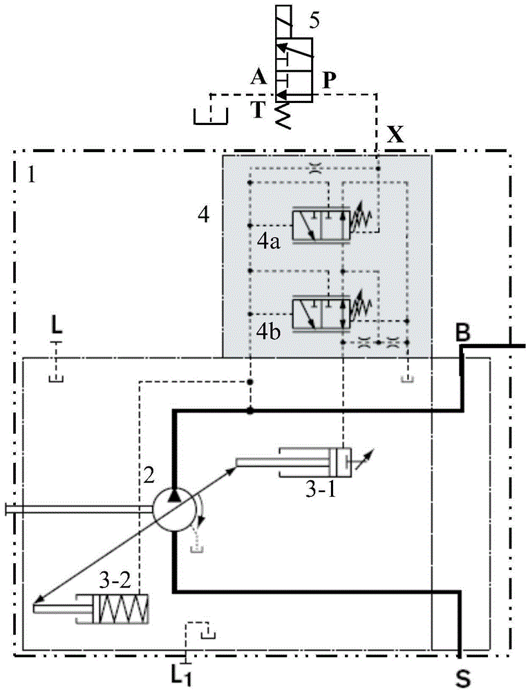
[0026] Such as figure 1 As shown, this embodiment is a variable hydraulic pump no-load starting device, the directional control valve is a two-position three-way directional control valve (5), and the variable hydraulic pump is a pressure-controlled variable hydraulic pump (1). The variable hydraulic pump (1) includes a hydraulic pump (2), a variable hydraulic cylinder (3) and a pressure control variable control device (4). A control port X is provided on the variable hydraulic pump (1), and the control port X of the pressure control variable control device (4) of the variable hydraulic pump (1) is connected to a two-position three-way directional control valve (5) with a small diameter. The P port of the two-position three-way directional control valve (5) is closed, the T port of the two-position three-way directional control valve (5) is connected to the fuel tank, and the first port of the variable hydraulic pump (1) The variable hydraulic cylinder (3-1) and the second va...

Embodiment 2

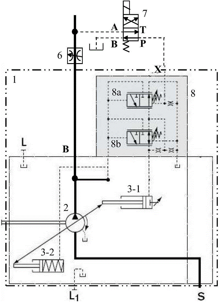
[0031] Such as figure 2 As shown, this embodiment is a variable hydraulic pump no-load starting device, the directional control valve is a two-position four-way directional control valve (7), and the variable hydraulic pump is a pressure / flow controlled variable hydraulic pump (1). The variable hydraulic pump (1) includes a hydraulic pump (2), a variable hydraulic cylinder (3) and a pressure / flow control variable control device (8). A control port X is provided on the variable hydraulic pump (1), and the control port X of the pressure / flow control variable control device (8) of the variable hydraulic pump (1) is connected to a two-position four-way directional control valve with a small diameter ( 7) Port P, the A port of the two-position four-way directional control valve (7) is connected to the outlet of the throttle valve (6), and the B port of the two-position four-way directional control valve (7) is connected to the oil tank, so The T port of the two-position four-way ...

Embodiment 3

[0036] Such as Figure 5 As shown, this embodiment is a variable hydraulic pump no-load starting device, the directional control valve is a two-position three-way directional control valve (5), and the variable hydraulic pump is a pressure / flow / power controlled variable hydraulic pump (1). The variable hydraulic pump (1) includes a hydraulic pump (2), a variable hydraulic cylinder (3) and a pressure / flow / power variable control device (9). A control port X is provided on the variable hydraulic pump (1). The pressure / flow / power control of the variable hydraulic pump (1) controls the control port X of the variable control device (9). The P port of the valve (5), the A port of the two-position three-way directional control valve (5) is connected to the outlet of the throttle valve (6), and the T port of the two-position three-way directional control valve (5) is connected to the oil tank , the B outlet of the variable hydraulic pump (1) is connected to the inlet of the throttle v...


PUM


Abstract

The invention relates to a non-load starting device and method for a variable hydraulic pump and belongs to the fields of fluid transmission and control. The non-load starting device for the variable hydraulic pump comprises the variable hydraulic pump and a little-channel direction control valve, wherein the variable hydraulic pump is provided with a control port X, and the direction control valve is used for performing unloading on an X port oil path of a variable control device of the variable hydraulic pump. During starting, unloading of the X port oil path of the variable control device is achieved through the direction control valve, so the displacement of the variable hydraulic pump can return to zero quickly. In the process of converting a stating state into a normal working state, the X port oil path of the variable control device can be in a non-load state through the control action of the direction control valve, and therefore the variable hydraulic pump can enter the normal working state. The invention further discloses a non-load starting method for the variable hydraulic pump. The non-load starting device is simple and reliable in structure, small in system impact pressure, free of flow overflowing power loss and suitable for non-load starting of variable hydraulic pumps with large displacement or small displacement.

Description

technical field [0001] The invention relates to a hydraulic pump starting device and method, in particular to a variable hydraulic pump no-load starting device and method, belonging to the field of fluid transmission and control. Background technique [0002] The hydraulic pump is an essential energy device for the hydraulic system, which provides oil with pressure energy for the hydraulic system. During the working process, in order not to damage the hydraulic pump and the power unit driving the hydraulic pump, the hydraulic pump must be started and operated under no-load conditions, that is, the starting torque of the hydraulic pump is very small. Usually, the no-load start of the hydraulic pump is: when starting, the output oil of the hydraulic pump directly flows back to the oil tank through the action of hydraulic components such as electromagnetic overflow valve, electromagnetic directional valve, and electro-hydraulic directional valve, and the output oil hydraulic pr...

Claims


Application Information

Patent Timeline
IPC IPC(8): F15B20/00F15B13/02
CPCF15B13/0401F15B2211/20546F15B2211/505
Inventor 彭熙伟郑戍华王向周
Owner BEIJING INSTITUTE OF TECHNOLOGYGY
Why Eureka
Try Eureka