
Detection method for decentered Gaussian beams emitted by fiber beam expanding collimating lens barrel

A Gaussian beam and detection method technology, applied in image data processing, instruments, calculations, etc., can solve the problems of power fluctuation, high cost, measurement error, etc., and achieve the effect of rapid detection, simple method and high reliability

Inactive Publication Date: 2015-04-22
NAT TIME SERVICE CENT CHINESE ACAD OF SCI
View PDF2 Cites 13 Cited by
  • Summary
  • Abstract
  • Description
  • Claims
  • Application Information

AI Technical Summary

Problems solved by technology

It is very difficult for the small hole scanning method to ensure that the moving direction of the small hole is perpendicular to the mechanical axis of the lens barrel, and it is also difficult to ensure that the moving track of the small hole is the diameter of the circular laser spot, so it is difficult to accurately obtain the direction perpendicular to the mechanical axis of the lens barrel. The results of the intensity distribution of the spot; and the small hole scanning method takes a long time. Although it can be detected after the laser power is stable, there will inevitably be power fluctuations during the long-term detection process, resulting in measurement errors, and a set of laser power is required to stabilize the laser power. Expensive feedback control system; although the pinhole scanning method can obtain Gaussian curves of light intensity distribution in two orthogonal directions, it cannot accurately reflect whether the maximum position of the Gaussian beam light intensity coincides with the mechanical axis of the lens barrel or other The degree of deviation from the mechanical axis

Method used


Image

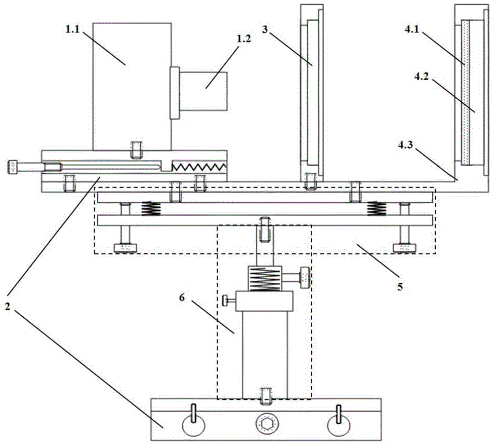
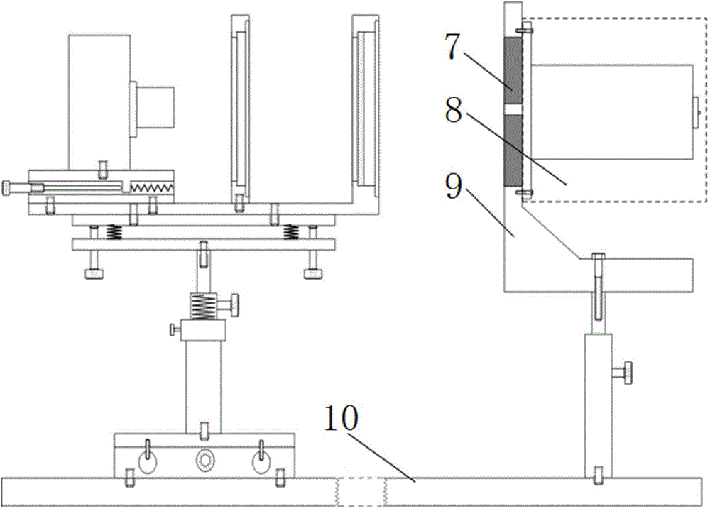
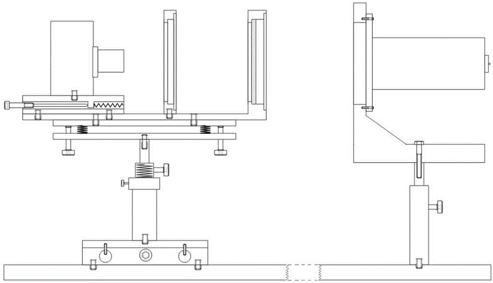
  • Detection method for decentered Gaussian beams emitted by fiber beam expanding collimating lens barrel
  • Detection method for decentered Gaussian beams emitted by fiber beam expanding collimating lens barrel
  • Detection method for decentered Gaussian beams emitted by fiber beam expanding collimating lens barrel

Examples


Embodiment Construction

[0032] The present invention will be further described below in conjunction with the accompanying drawings and embodiments, and the present invention includes but not limited to the following embodiments.

[0033] The invention uses CCD imaging and image processing technology to realize the detection of the eccentric Gaussian beam, and has the advantages of low cost, high precision and fast detection.

[0034] The present invention is based on the theory of eccentric Gaussian beams:

[0035] 1. Abdul-Azeez R.Al-Rashed and Bahaa E.A.Saleh, Decentered Gaussian beams [J], APPLIED OPTICS, 1995, Vol.34(30): 6819-6825

[0036] 2. Claudio Palma, Decentered Gaussian beams, ray bundles, and Bessel-Gauss beams [J]. APPLIED OPTICS, 1997, Vol.36(6): 1116-1120.

[0037] 3. Ji Xiaoling, Lu Baida. Transformation characteristics of Gaussian beam passing through inclined optical elements[J]. Laser Technology, 2001, Vol.25(5): 351-355.

[0038] 4. Zhou Shengguo, Shen Xueju. Analysis of the In...


PUM


Abstract

The invention provides a detection method for decentered Gaussian beams emitted by a fiber beam expanding collimating lens barrel. The detection method includes the three steps of constructing a CCD photographic device, adjusting a mechanical axis of the to-be-detected lens barrel to be perpendicular to an image acquisition plane and conducting image acquisition, processing and decentered detection. According to the method, uneven distribution of intensity of light perpendicular to the section of the mechanical axis caused by decentered Gaussian beams generated by off-axis imbalance of an optical element can be effectively detected, distribution data of the intensity of the light perpendicular to the section of the mechanical axis of the lens barrel can be accurately obtained, detection can be rapidly conducted, and distribution information of the intensity of the light perpendicular to the section of the mechanical axis in different directions can be obtained. The detection method has the advantages of being simple, practical, high in reliability and the like and can be applied and popularized in the cold atom research field, the fountain clock research field and laser transmission engineering.

Description

technical field [0001] The invention belongs to the technical field of photoelectric precision detection and can be used for the detection of eccentric Gaussian beams emitted by optical fiber beam expansion collimating lens barrels. Background technique [0002] In the research field of cold atomic fountain clocks, the laser beam used in the magneto-optical trap is produced by a fiber beam expander collimator. The preparation of cold-atom samples is crucial. Under the ideal condition that each optical device is not misaligned, the wave vector of the wavefront of the exit beam of the fiber beam expander collimator lens barrel should be parallel to the optical axis of the beam expander collimator optical system (that is, the mechanical axis of the lens barrel); The spot size on the section perpendicular to the mechanical axis of the lens barrel is constant along the direction of the mechanical axis; the trajectory of the maximum light intensity of the outgoing beam should be ...

Claims


Application Information

Patent Timeline
Patent Type & Authority Applications(China)
IPC IPC(8): G06T7/00G06T7/60
CPCG06T7/0008G06T7/60G06T2207/10052G06T2207/20076G06T2207/30108
Inventor 林睿张首刚阮军王心亮刘丹丹陈江张辉管勇余凤翔施俊如周聪华
Owner NAT TIME SERVICE CENT CHINESE ACAD OF SCI
Learn More