

High temperature sintered electrode paste for led glass filament
A technology of LED glass, high temperature sintering, applied in the direction of conductive materials dispersed in non-conductive inorganic materials, etc., to achieve good thermal expansion matching, high printing resolution, and good solder resistance.
Active Publication Date: 2017-05-17
广州市尤特新材料有限公司
View PDF1 Cites 0 Cited by
- Summary
- Abstract
- Description
- Claims
- Application Information
AI Technical Summary
Problems solved by technology
There is no such targeted product in the prior art
Method used
View moreImage
Smart ImageViewing Examples

Examples
Embodiment 1
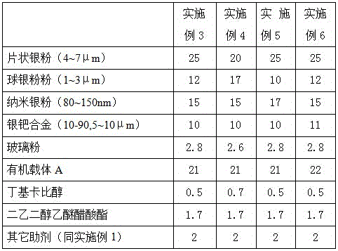
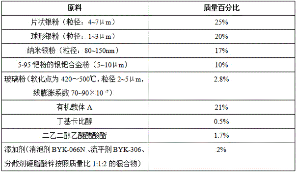
[0031] The high-temperature sintering electrode paste for LED glass filament, its formula composition is as follows:
[0032] Table 1:
[0033]
[0034] Among them, organic carrier A is composed by mass: ethyl cellulose 4%, hydrogenated castor oil 3%, castor oil 1%, terpineol 35%, butyl carbitol 37%, diethylene glycol ether acetate 20% .
Embodiment 2
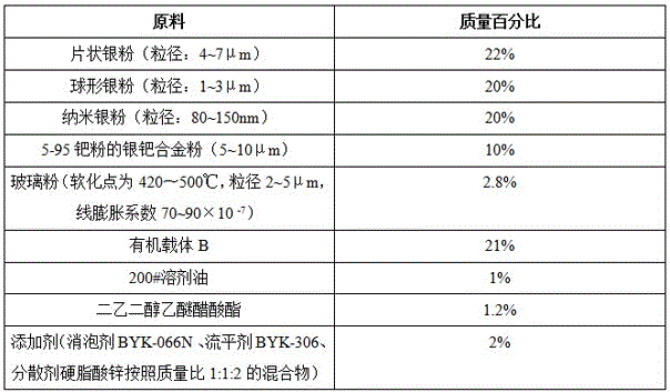
[0036] The high-temperature sintering electrode paste for LED glass filament, its formula composition is as follows:
[0037] Table 2:
[0038]
[0039] The organic carrier B is composed by mass: 3% ethyl cellulose, 5% PVB, 2.5% hydrogenated castor oil, 43% terpineol, and 46.5% butyl carbitol.
Login to View More PUM
| Property | Measurement | Unit |
|---|---|---|
| softening point | aaaaa | aaaaa |
| particle diameter | aaaaa | aaaaa |
| particle diameter | aaaaa | aaaaa |
Abstract
The invention discloses high temperature sintering electrode slurry for an LED glass filament. The high temperature sintering electrode slurry for the LED glass filament is composed of, by mass, 65-75 percent of metal conductive filler, 2-4 percent of inorganic bond, 20-30 percent of organic carriers, 3-5 percent of additives and the balance diluent. The high temperature sintering electrode slurry for the LED glass filament has the advantages of being high in printing resolution ratio, being compact in electrode after sintering, and having good adhesive force for tempered glass, ceramics and similar base materials. An electrode is good in appearance after being sintered, has good electrical conductivity, stability and weather resistance, can be bonded with a metal wire with the pulling force lager than 8 grams, can be welded and is good in soldering resistance.
Description
technical field [0001] The invention relates to a high-temperature sintering electrode slurry for LED glass filaments. Background technique [0002] Traditional LED brackets are generally made of copper, iron, aluminum or ceramics as substrates, followed by a series of processes such as sintering, stamping, cutting, electroplating, and injection molding. The electrodes of traditional LED glass brackets are generally made by low-temperature curing. The adhesion between the electrodes and the glass is not good, and it is easy to scratch and fall off. At the same time, the welding performance is extremely poor. The soldering temperature of the solder is generally around 250 ° C. The old glass brackets are soldered on the electrodes. When welding the conductive electrode material, it is very easy to weld off the entire electric plate, resulting in scrapping of the bracket. When the old glass bracket is still packaged, the pulling force of bonding the metal wire on the electrode...
Claims
Login to View More Application Information
Patent Timeline
 Patent Type & AuthorityPatents(China)
IPC IPC(8): H01B1/22
Inventor朱鑫陈伟陈海文周昭寅
Owner广州市尤特新材料有限公司