Image forming apparatus

Active Publication Date: 2010-12-02
SHARP KK
View PDF1 Cites 0 Cited by
  • Summary
  • Abstract
  • Description
  • Claims
  • Application Information

AI Technical Summary

Benefits of technology

[0022]It is therefore an object of the present invention to provide an image forming apparatus that is unlikely to experience photo-deterioration accompanied by use over a long period of time and that allows stable printing for high printing resolution.
[0023]The inventors of the present invention have made intensive studies and efforts to solve the above-described problems and, as a result, found that use of an exposure means and a discharge means for providing exposure light and discharge light that are different in wavelength, and use of a charge generation material having absorption of light in both short wavelength and long wavelength regions for a photoconductor can solve the above-described problems to complete the present invention.

Problems solved by technology

Accordingly, in image forming apparatuses that perform exposure with light having a short wavelength and discharge with light having a short wavelength, photoconductors are always exposed to light having a short wavelength, and the performance thereof deteriorates due to photo-deterioration as used over a period of time to cause degradation of images.

Method used


Image

  • Image forming apparatus
  • Image forming apparatus
  • Image forming apparatus

Examples


production example 1

Production of Titanylphthalocyanine

[0132]A diiminoisoindoline in an amount of 29.2 g and sulfolane in an amount of 200 ml were mixed, and titanium tetraisopropoxide in an amount of 17.0 g was added thereto to be reacted under a nitrogen atmosphere at 140° C. for 2 hours. A precipitate was filtered off after cooling, and washing with chloroform, washing with a 2% aqueous hydrochloric acid solution, washing with water, washing with methanol, and drying were performed to obtain 25.5 g of a titanylphthalocyanine (yield 88.5%) represented by the following formula:

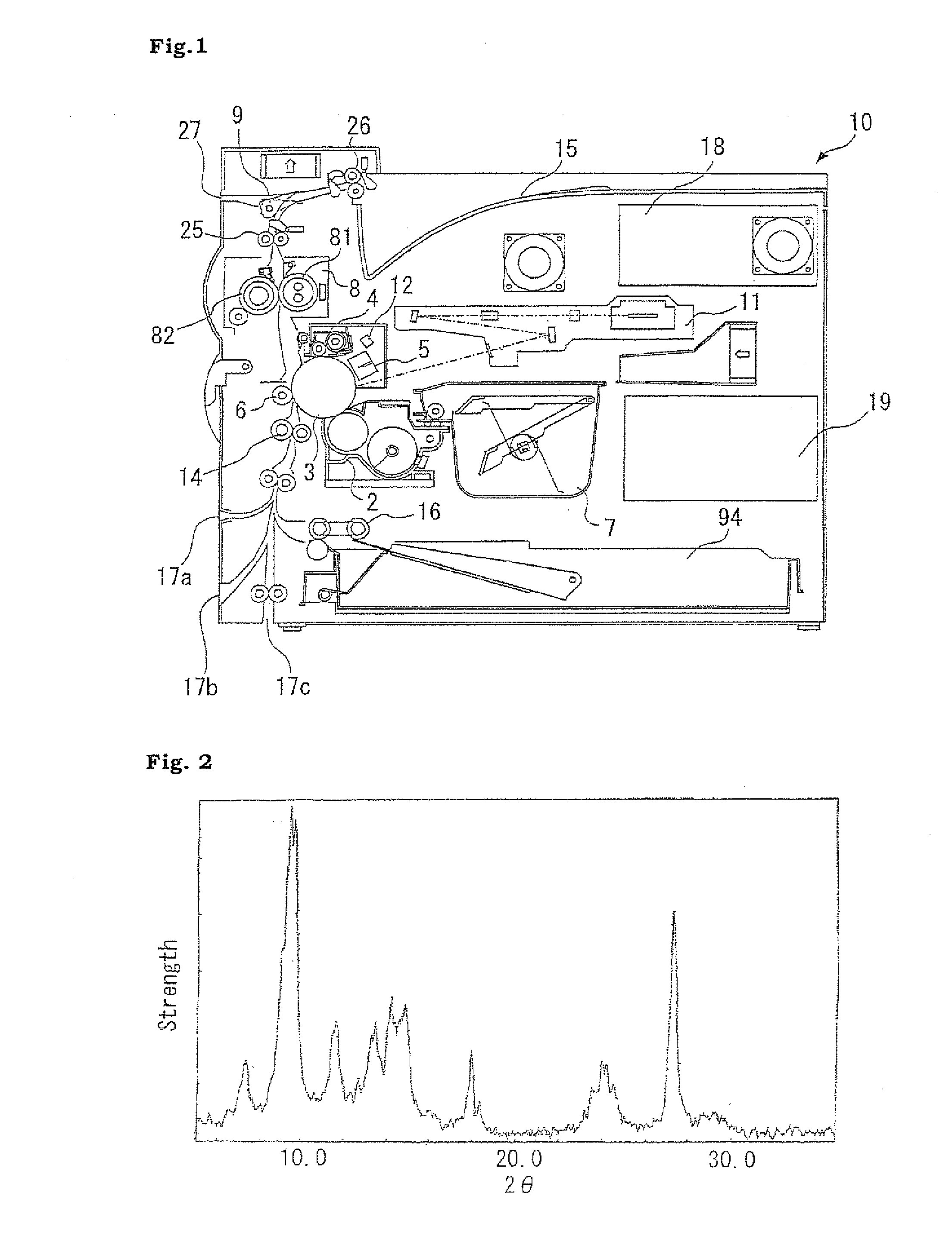
[0133]The titanylphthalocyanine obtained was confirmed to be a crystalline titanylphthalocyanine having major peaks in an X-ray diffraction spectrum for CuKα characteristic X-rays (wavelength: 1.5418Å) at Bragg angles (2θ±0.2°) of 7.3°, 9.4°, 9.6°, and 27.2°, in which a peak bundle formed by overlapping the peaks at 9.4° and 9.6° is the largest peak, and the peak at 27.2° is the second largest peak as illustrated in FIG. 2, and ...

production example 2

Production of Photoconductor A

[0134]The photoconductor A was produced according to the following method.

[0135]A titanium oxide (trade name: TIPAQUE® TTO-D-1, product by ISHIHARA SANGYO KAISHA, LTD.) in an amount of 3 parts by weight and a commercially available polyamide resin (trade name: AMILAN® CM8000, product by Toray Industries, Inc.) in an amount of 2 parts by weight were added to methyl alcohol in an amount of 25 parts by weight and dispersed with the use of a paint shaker for 8 hours to produce 3 kg of a coating solution for undercoat layer formation. The coating solution for undercoat layer formation obtained was subjected to cutting (processed into a ten-point surface roughness RzJIS according to JISB-0601 of 0.80 μm), and then applied to an aluminum conductive support with a washed surface having a diameter of 80 mm and a length of 348 mm by a dipping coating method to form an undercoat layer having a film thickness of 1 μm.

[0136]The titanylphthalocyanine obtained in Prod...

production example 3

Production of Photoconductor B

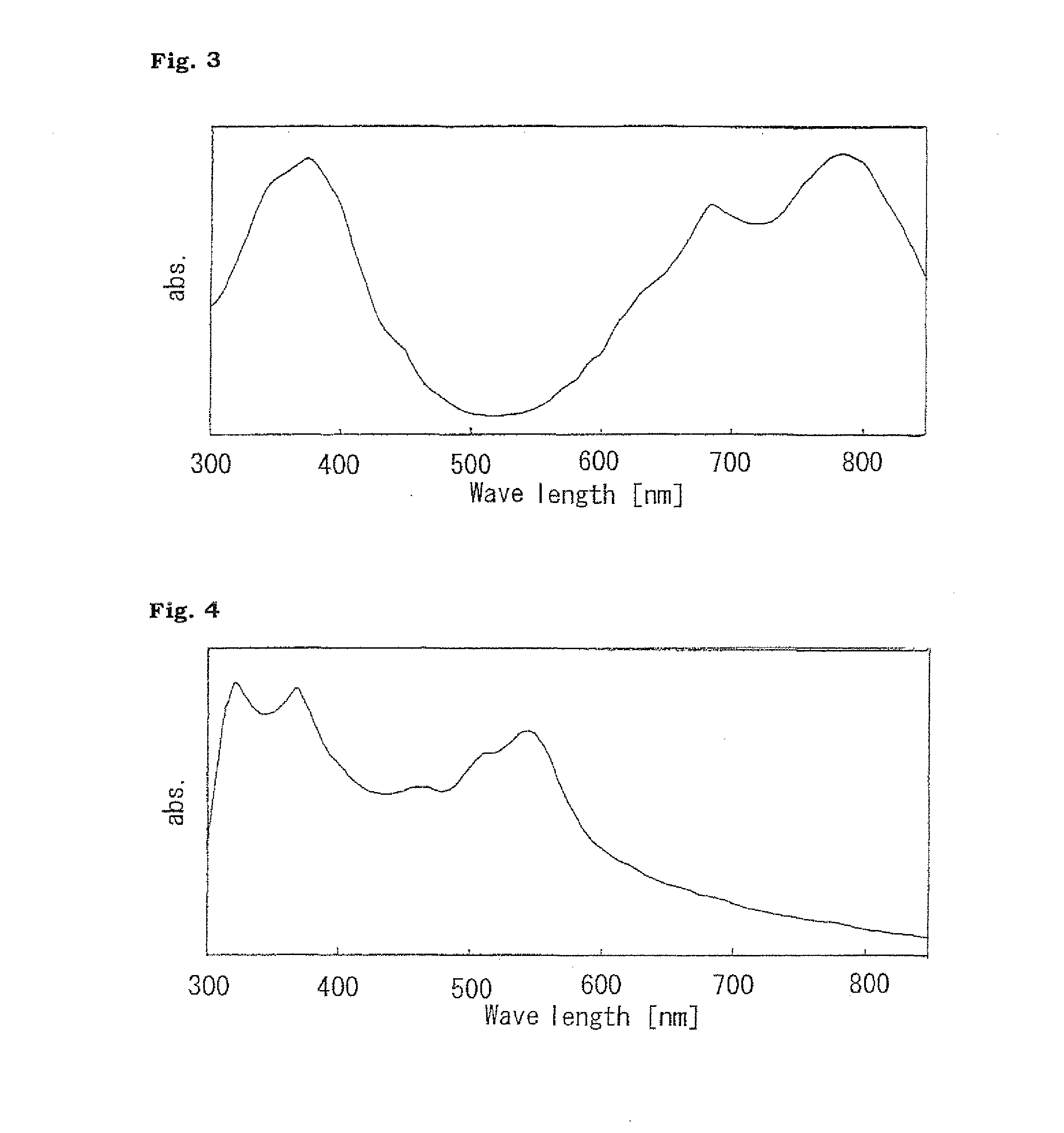
[0139]The photoconductor B was produced in the same manner as in the method for producing the photoconductor A in Production Example 2 except that a dibromoanthanthrone (model number: D01148, product by ZENECA limited) having absorbance as illustrated in FIG. 4 was used instead of the titanylphthalocyanine used as the charge generation material.


PUM


Abstract

The present invention therefore provides an image forming apparatus, comprising: a photoconductor; a charge means for charging the photoconductor; an exposure means for irradiating a surface of the photoconductor with light to form an electrostatic latent image; a development means for developing the electrostatic latent image formed; a transfer means for transferring the image developed onto a paper sheet; and a discharge means for irradiating the surface of the photoconductor with light to eliminate charges, wherein the photoconductor contains a titanylphthalocyanine having absorption bands in a wavelength region of 380 nm to 420 nm and a wavelength region of 600 nm to 850 nm as a charge generation material, the exposure means irradiates the surface of the photoconductor with light having a wavelength of 380 nm to 420 nm to form the electrostatic latent image, and the discharge means irradiates the surface of the photoconductor with light having a wavelength of 600 nm to 850 nm to eliminate the charges.

Description

CROSS-REFERENCE TO RELATED APPLICATION[0001]This application is related to Japanese Patent Application No. 2009-126403 filed on 26 May, 2009, whose priority is claimed under 35 USC §119, and the disclosure of which is incorporated by reference in its entirety.BACKGROUND OF THE INVENTION[0002]1. Field of the Invention[0003]The present invention relates to an electrophotographic image forming apparatus such as copying machines, facsimiles, and printers using an electrophotographic system.[0004]More particularly, the present invention relates to an electrophotographic image forming apparatus comprising: an exposure section using blue laser having a short wavelength as writing exposure light; a discharge section using red LED having a long wavelength as discharge light; and an electrophotographic photoconductor containing a charge generation material having absorption ranges for both the wavelengths.[0005]2. Description of the Related Art[0006]Image formation of an electrophotographic s...

Claims


Application Information

Patent Timeline
IPC IPC(8): G03G15/00
CPCG03G5/0696G03G15/75
Inventor YAMANAKA, TAKAYUKITORIYAMA, KOICHIFUKUSHIMA, KOTAROMATSUMOTO, MASANORI
Owner SHARP KK
Why Eureka
Try Eureka