Equipment and process for manufacturing power transmission conductor with carbon fiber core

A technology of transmission wire and production process, applied in cable/conductor manufacturing, conductors, circuits, etc., can solve the problems of difficulty in production, reduced safety, and greater harm to the safe operation of power transmission systems, and achieves good conductivity and transmission efficiency. safety effect

Active Publication Date: 2015-04-22
常州艾邦机械科技有限公司
View PDF9 Cites 11 Cited by
  • Summary
  • Abstract
  • Description
  • Claims
  • Application Information

AI Technical Summary

Problems solved by technology

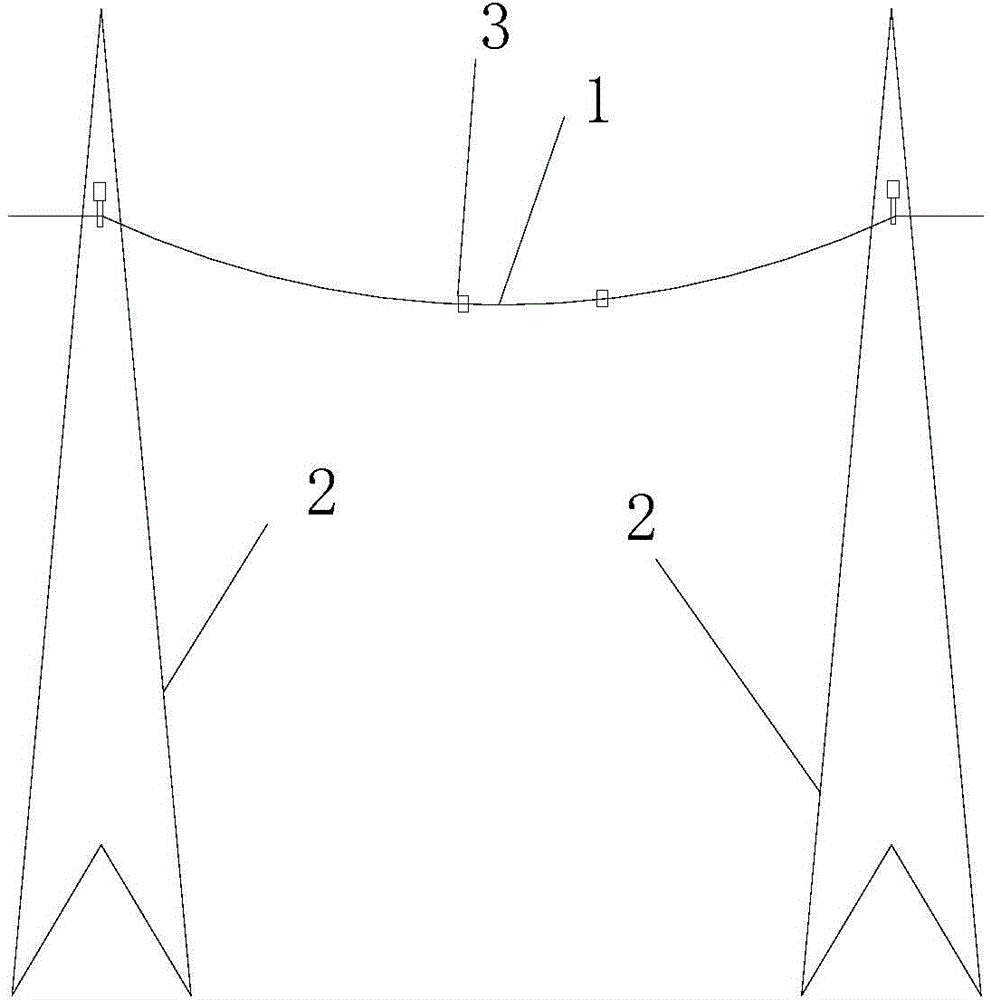
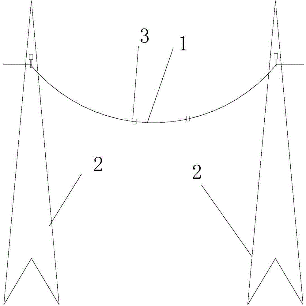
[0005] 1. Since the aluminum conductor layer is wrapped around the wire core by winding, it is difficult to make the wire core and the aluminum conductor layer fit tightly and firmly, that is, there will be a gap between the inner wall of the aluminum conductor layer and the outside of the wire core, that is The core can be pulled out of the aluminum conductor layer at will; in use, see figure 1 , 2 1. The power transmission line 1 is erected between two support towers 2 for electric energy transmission. Due to thermal expansion and contraction, the aluminum conductor layer will expand or contract; and due to the characteristics of low expansion and high temperature resistance of carbon fiber materials, in During use, the carbon fiber core basically maintains its original shape, without huge deformation, and its deformation is basically negligible; therefore, when the aluminum conductor layer expands, the length of the aluminum conductor layer will become longer and the diameter will increase, and the core will be more It is easy to pull out from the aluminum conductor layer, so that the entire transmission wire will produce obvious sag phenomenon, and if it is more serious, the expansion of the aluminum conductor layer will generate a force to push the supporting tower, prompting the supporting tower to tilt outward, reducing the safety of use; When the aluminum conductor layer shrinks, the length of the aluminum conductor layer will become shorter and the diameter will become smaller, which will generate a force that pulls the supporting tower to tilt inward, and also promotes the tilting of the supporting tower; The conductor layer only plays the role of hanging in mid-air, and does not restrain the aluminum conductor layer
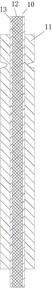
[0006] 2. The aluminum conductor layer is a plurality of aluminum conductors wound outside the wire core and arranged in a spiral counterclockwise direction along the wire core to form an aluminum conductor layer; since the aluminum conductor layer is formed by spirally winding multiple aluminum conductors, the adjacent aluminum conductors There will inevitably be gaps between them. During use, impurities and water will enter the gaps to form barriers and corrode, which will affect the conductivity of the wires and cause a large power loss. In order to meet the conductivity of the wires, it is necessary to increase the aluminum conductor layer. Cross-sectional area, which undoubtedly greatly increases the input cost of the wire
[0008] 4. Since the aluminum conductor layer is formed by winding the inner layer of the aluminum conductor and the outer layer of the aluminum conductor, the thickness of the aluminum conductor layer composed of double aluminum conductors is thicker, the cost is high, and the production is difficult. At the same time, the weight of the entire transmission line is increased, thereby further Sag Phenomenon During the Use of Earth-weighted Transmission Lines
[0009] 5. Since the existing aluminum conductor layer is spirally wound by multiple aluminum conductors, gaps will inevitably be formed between adjacent aluminum conductors; in this way, when the overhead transmission line is blown by the wind, the wind will enter the interior of the transmission line through the gap, The gas vortex is generated inside the transmission line, so that the gas stays in the transmission line for a long time, which will increase the swaying amplitude and frequency of the transmission line; because the transmission line needs to use the clamp 3 to prevent the loosening of the transmission line, the swaying of the transmission line During the process, the transmission line at the clamp is repeatedly bent, causing material fatigue, and finally leads to broken strands and disconnection accidents of the transmission line, which is harmful to the normal and safe operation of the transmission system, and the service life of the transmission line and the transmission system is relatively short
[0010] 6. Since there is no firm connection between the wire core and the aluminum conductor layer in the transmission line, and due to the long span and heavy weight of the overhead transmission line, the aluminum conductor layer takes the wire core to produce arc sag. When the aluminum conductor layer is bent and deformed, its cross-section The centroid produces linear displacement along the direction perpendicular to the axis, that is, deflection. Therefore, in the design of the pre-transmission system, the length of the transmission line after the sag needs to be considered; for example, an overhead transmission system of one kilometer needs at least 10 meters more Left and right transmission lines to overcome the problem of sag. If the total length of transmission lines used in a regional power grid is 1,000 kilometers, an additional 10 kilometers of transmission lines are required. If a meter of transmission lines is worth 100 yuan, an additional 1 million yuan is required. Increased input costs for the transmission grid

Method used


Image

  • Equipment and process for manufacturing power transmission conductor with carbon fiber core
  • Equipment and process for manufacturing power transmission conductor with carbon fiber core
  • Equipment and process for manufacturing power transmission conductor with carbon fiber core

Examples


Embodiment Construction

[0055] In order to have a clearer understanding of the technical features, purposes and effects of the present invention, the specific implementation of the present invention will now be described in detail in conjunction with the accompanying drawings. Apparently, the described embodiments are some, not all, embodiments of the present invention. Based on the embodiments of the present invention, all other embodiments obtained by persons of ordinary skill in the art without making creative efforts belong to the protection scope of the present invention.

[0056] see Figure 3-10 , a power transmission wire with a carbon fiber core, including a carbon fiber core rod 10, a metal conductive layer 11 outside the carbon fiber core rod, the metal conductive layer is an integral metal tube that is sleeved on the carbon fiber core rod to completely surround the carbon fiber core rod, carbon fiber The outer surface of the mandrel and the inner surface of the metal conductive layer are...


PUM


Abstract

The invention relates to the technical field of overhead power transmission conductors, and in particular relates to equipment and a process for manufacturing a power transmission conductor with a carbon fiber core. The power transmission conductor with the carbon fiber core comprises a carbon fiber core rod and a metal conductive layer, wherein the metal conductive layer is arranged outside the carbon fiber core rod; the metal conductive layer is an overall metal tube which sleeves the carbon fiber core rod and is used for completely wrapping the carbon fiber core rod; the outer surface of the carbon fiber core rod and the inner surface of the metal conductive layer are integrally formed in an extrusion manner. In the process that an aluminum conductor layer is expanded or shrunk, the metal conductive layer is not expanded to two ends or shrunk due to limit of the carbon fiber core rod, so that the length of the metal conductive layer is not changed, the outer diameter of the metal conductive layer is changed at most, sag is not caused by change of the outer diameter, the metal conductive layer is free of force for pulling or pushing a support tower, and the use security of the power transmission conductor is ensured.

Description

technical field [0001] The invention relates to the technical field of overhead power transmission wires, in particular to equipment and technology for manufacturing power transmission wires with carbon fiber cores. Background technique [0002] The cable is usually made of several or several groups of conductors (at least two in each group) twisted around a center, which is shaped like a rope, and the outer layer is covered with a high insulation layer; and the transmission conductor is generally a steel-cored aluminum conductor. Formed and erected between transmission towers for power transmission. Therefore, the transmission conductor is different from the cable. [0003] The power transmission of traditional overhead transmission conductors is carried out through steel-cored aluminum conductors. Since such conductors are greatly affected by temperature during power transmission, sag problems will occur, so steel-reinforced aluminum conductors have gradually been replace...

Claims


Application Information

Patent Timeline
Patent Type & Authority Applications(China)
IPC IPC(8): H01B9/00H01B7/18H01B5/06H01B13/00
Inventor 束邦俊刘春山
Owner 常州艾邦机械科技有限公司
Why Eureka
Try Eureka