Noncontact-type tear film breakup time measuring device and method

A burst time, non-contact technology, which is applied in the fields of eye testing equipment, medical science, diagnosis, etc., can solve the problems of poor consistency and repeatability of measurement results, discomfort of the examinee, and poor objectivity of measurement results, etc. Discomfort, good repeatability, objective and accurate measurement results

Inactive Publication Date: 2015-04-29
XIAMEN UNIV
View PDF5 Cites 21 Cited by
  • Summary
  • Abstract
  • Description
  • Claims
  • Application Information

AI Technical Summary

Problems solved by technology

This measurement method has the following three deficiencies: (1) after sodium fluorescein is injected into the tear film, it affects the stability of the tear film, causing the tear film to be different from the tear film in the natural state, and the concentration of the dripped sodium fluorescein Different degrees of tear film stability will affect the tear film stability, making the measurement results less objective; (2) The doctor uses a stopwatch to time the measurement, and the results obtained by different doctors will be slightly different. poor consistency and repeatability; (3) invasive diagnosis can easily bring discomfort to the examinee

Method used


Image

  • Noncontact-type tear film breakup time measuring device and method
  • Noncontact-type tear film breakup time measuring device and method
  • Noncontact-type tear film breakup time measuring device and method

Examples


Embodiment 1

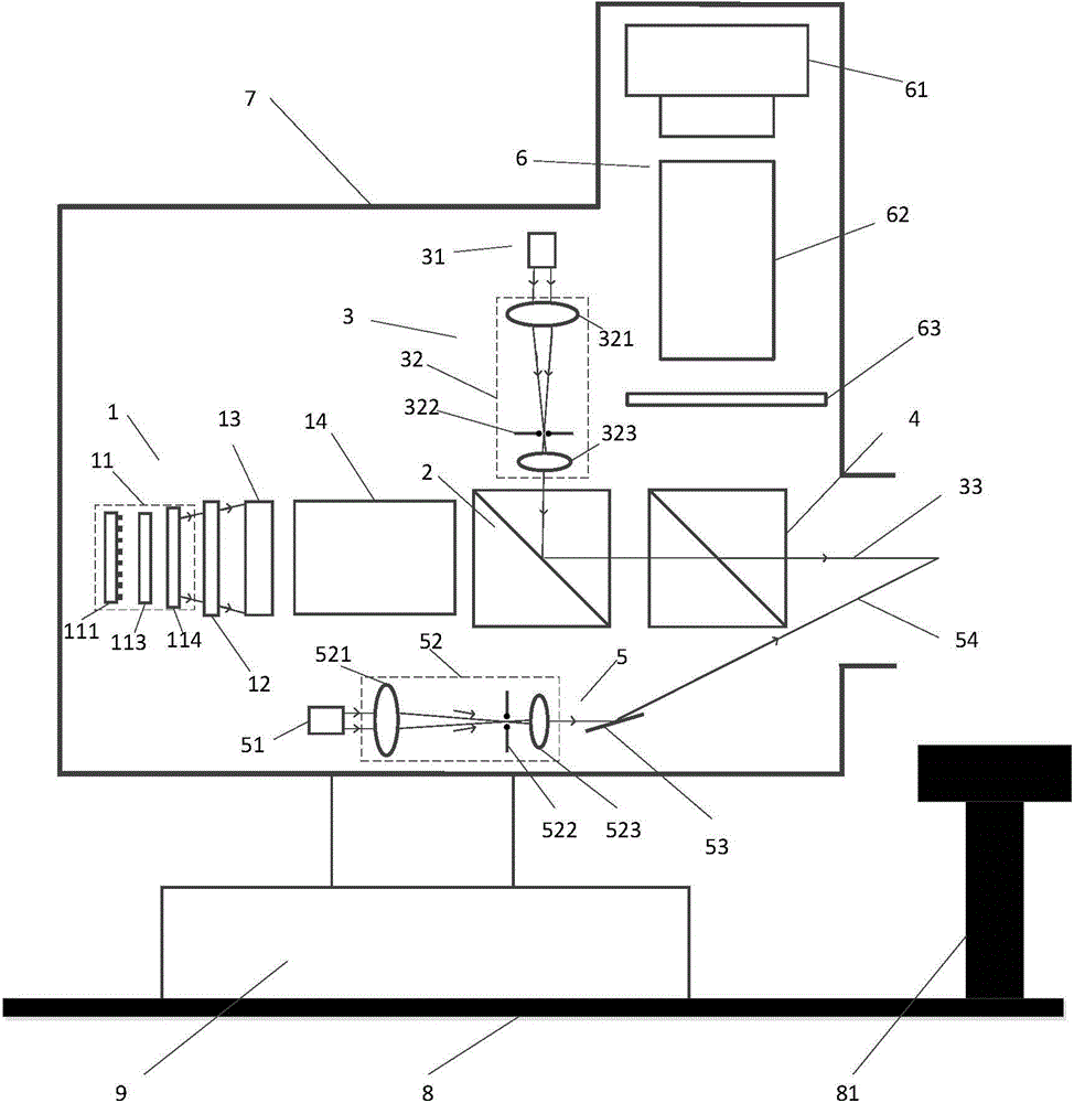
[0037] The following combination Figure 1-6 This embodiment will be described.

[0038] Such as figure 1 As shown, the device of the present invention is provided with a structured light projection unit 1, a first beam splitter 2, a center positioning unit 3, a second beam splitter 4, a focusing unit 5, an imaging unit 6, a housing 7, a base 8, and three-dimensional motion Station 9, motion controller and host computer. The three-dimensional motion platform 9 is arranged on the base 8, the shell 7 is arranged on the three-dimensional motion platform 9, and the motion controller is connected with the three-dimensional motion platform 9 and the upper computer. A detection window is provided on the side of the housing 7 and a chin rest 81 is provided on the base 8 to support the head of the subject. The structured light projection unit 1, the first beam splitter 2, the second beam splitter 4 are sequentially spaced along the horizontal direction, and the second beam splitter 4 is...

Embodiment 2

[0044] The following combination Figure 7 , Figure 8 Describe this embodiment

[0045] Such as Figure 7 As shown, the main technical features of the present invention are the same as that of Embodiment 1, and the difference lies in the following four parts: the illumination unit 11, the beam modulator 13, the center positioning light source 31, and the focusing light source 51. In this embodiment, the illumination unit 11 includes an illumination light source 111 and a beam expander 112. The illumination light source 111 is a near-infrared laser with an emission wavelength of 808 nm. After the laser beam is expanded by the beam expander 112, it passes through the first polarizer 12. It becomes linearly polarized light and provides background illumination for the beam modulator 13. The beam modulator 13 is a programmable spatial light modulator, which can be programmed to control the liquid crystal orientation of each liquid crystal pixel to control whether light can pass throu...


PUM


Abstract

The invention relates to a noncontact-type tear film breakup time measuring device and method. The noncontact-type tear film breakup time measuring device comprises a structured light projection unit, a first light splitter, a central positioning unit, a second light splitter, a focusing unit, an imaging unit, a shell, a base and a three-dimensional moving platform, the structured light projection unit projects structured light patterns of a certain mode to the surface of a tear film, structured light images modulated by the surface of the tear film are collected by the imaging unit, and whether the structured light patterns in the collected images are distorted or broken or not is detected through upper computer software so as to judge thinning and breaking conditions of the tear film. Tear film breakup time is measured by adopting a method of structured light detection, so that stability of the tear film is unaffected due to a noncontact measuring mode; the device can automatically recognize starting point and finishing point of tear film breakup time measuring to automatically complete the whole measuring process, thereby being objective and accurate in measuring result.

Description

Technical field [0001] The invention relates to a medical optical measuring device and a measuring method, in particular to a non-contact tear film breaking time measuring device and method. Background technique [0002] The surface of normal human eyes is covered by a layer of tear film. A stable tear film can maintain the health of the eye surface, keep the eye surface moist, and improve the refractive system of the eye. The tear film is the outermost barrier of the human eye and an important part of the ocular surface immune defense system. The instability of the tear film will destroy the integrity of the tear film barrier, and bacterial toxins and antigenic substances are likely to directly contact the corneal epithelium. , Leading to the immune pathological reaction and damage of the cornea. Human eyes apply tear fluid to the surface of the eyeball by blinking to form a tear film. After the tear film is formed, it begins to evaporate, causing local thinning and rupture. T...

Claims


Application Information

Patent Timeline
Patent Type & Authority Applications(China)
IPC IPC(8): A61B3/15
Inventor 张陈涛张建寰颜黄苹刘婷婷陶金
Owner XIAMEN UNIV
Why Eureka
Try Eureka