Technological method for screw manufacturing through laser combination

A process method and screw technology, applied in the field of screw laser combination manufacturing, can solve the problems of easy wear of metal screws, short service life, large machining allowance, etc., and achieve simple process method and manufacturing cost, improved service life, and anti-wear performance. improved effect

Active Publication Date: 2015-04-29
ZHEJIANG UNIV OF TECH +1
View PDF9 Cites 10 Cited by
  • Summary
  • Abstract
  • Description
  • Claims
  • Application Information

AI Technical Summary

Problems solved by technology

[0004] The purpose of the present invention is to solve the problems of existing metal screws such as easy wear, short service life, and large processing allowance, and provide a metal screw processing technology for laser combined manufacturing with high bonding strength with the substrate, long service life, and small processing allowance.

Method used


Image

  • Technological method for screw manufacturing through laser combination
  • Technological method for screw manufacturing through laser combination
  • Technological method for screw manufacturing through laser combination

Examples


Embodiment 1

[0032] The type of the processed screw is SCM, the material is 42CrMo round steel, and the processing state is quenched and tempered. Before laser treatment, customize the fixture and pre-determine the treatment area and overlap; then perform CNC programming according to the specific size of the screw to be treated; clean the area to be treated on the surface of the screw.

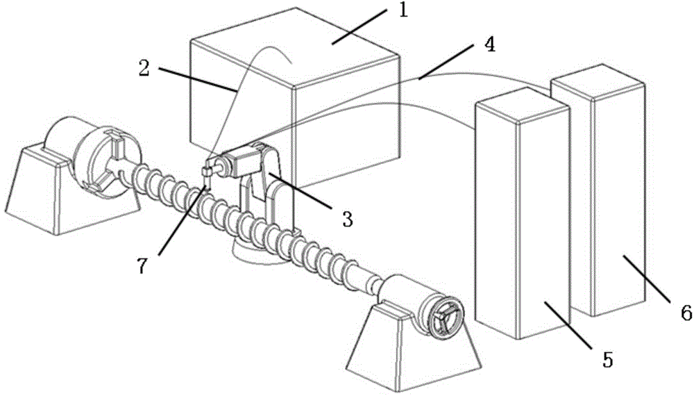
[0033] Put the Ni60 powder and the 42CrMo powder into the oven respectively, and carry out the drying treatment at 200°C for 2 hours. After the treatment is completed, the dried powder can be put into the first powder feeder 5 and the second powder feeder 6 respectively for use, and the particle size of the above alloy powder is spherical powder of -140~+325 mesh;

[0034] The following takes the surface treatment of the metal screw of the FT-130 injection molding machine as an example. The specific steps are as follows:

[0035] 1. Install the metal screw with a three-jaw chuck and a thimble.

[0036] 2...

Embodiment 2

[0054] The type of the processed screw is SCM, the material is 42CrMo round steel, and the processing state is quenched and tempered. Before laser treatment, customize the fixture and pre-determine the treatment area and overlap; then perform CNC programming according to the specific size of the screw to be treated; clean the area to be treated on the surface of the screw.

[0055] Put the Stellite 6 powder and 35CrMo powder into the oven, and dry them at 200°C for 2 hours. After the treatment is completed, the dried powder can be put into the first powder feeder 5 and the second powder feeder 6 respectively for standby; the particle size of the above-mentioned alloy powder is a spherical powder of -140~+325 mesh.

[0056] 1. Install the metal screw with a three-jaw chuck and a thimble.

[0057] 2. Clean the parts to be treated: remove oil stains with acetone, pine water, etc.

[0058] 3. According to the processing requirements, carry out numerical control programming accor...


PUM

PropertyMeasurementUnit
particle sizeaaaaaaaaaa

Abstract

The invention relates to the field of material science and laser processing, in particular to a technological method for screw manufacturing through laser combination. The technological method sequentially comprises the following steps of determining a laser combination additive manufacturing material; cleaning the surface of a polished rod of a screw; carrying out laser combination additive manufacturing on the screw; and carrying out subsequent milling on the primarily formed screw. The technological method disclosed by the invention has the beneficial technical effects that the polished rod of the screw is subjected to additive manufacturing by using a laser combination additive manufacturing technology; the surface to be processed is rapidly scanned by a laser beam with high-energy density; due to extremely rapid heating and cooling speeds, crystal particles are not easy to grow, so that a high-performance surfacing layer which has extremely fine crystal grains and is in firm metallurgical bonding with a matrix body is obtained on the screw flight surface formed by laser combination additive manufacturing. When a material of a superficial layer is changed (for instance, Ni60 is changed into Stellite 6 and 316L combination), the performances of the superficial layer can be changed, and the technological method can be applied in other occasions (such as large-size gears).

Description

【Technical field】 [0001] The present invention relates to the field of material science and laser processing, in particular to a process method for screw laser combined manufacturing, especially suitable for screw surface bearing complex stress from various forms including friction and extrusion. Fatigue damage and failure, extending the life of the screw. 【Background technique】 [0002] "Laser combined additive manufacturing technology" is a technology developed on the basis of "additive manufacturing" (commonly known as "3D printing"). Forming digital manufacturing technology, its principle is to use energy to melt and sinter metal powder to form new metal materials and shapes. The combination of laser combined additive manufacturing and traditional manufacturing methods emphasizes the difference from the base material, the multi-component functional structure, the combination of heterogeneous materials, and the gradient change of the materials inside the manufacturing la...

Claims


Application Information

Patent Timeline
Patent Type & Authority Applications(China)
IPC IPC(8): B22F3/105B22F5/06B22F7/08
CPCY02P10/25
Inventor 姚建华董刚
Owner ZHEJIANG UNIV OF TECH
Why Eureka
Try Eureka