
An Atmospheric Pressure Surface Discharge Plasma Device for Surface Modification of Glass and Polymer Materials

A polymer material and surface modification technology, applied in the field of material surface treatment, can solve the problems of low plasma efficiency, difficult to obtain plasma, and low breakdown voltage on the surface of the discharge medium, and achieve improved hydrophilicity and high industrial efficiency. The effect of promoting value and improving the surface energy of materials

Active Publication Date: 2017-06-23
DALIAN UNIV OF TECH
View PDF7 Cites 2 Cited by
  • Summary
  • Abstract
  • Description
  • Claims
  • Application Information

AI Technical Summary

Problems solved by technology

The electrode structure of this creeping discharge plasma generator has many evolved forms. For example, the electrode shape on one side of the dielectric plate is comb-shaped, and another comb-shaped electrode interlaced with it is arranged on the other side of the dielectric plate or is A whole sheet metal electrode is attached to the other side of the dielectric plate. Through the uniform arrangement of multiple sets of electrode pairs on the surface of the dielectric plate, a relatively uniform and large-area plasma layer can be generated on the surface of the medium. This surface discharge plasma occurs The device makes up for the defects of the first dielectric barrier discharge plasma generator, but because most of the applied voltage is divided by the capacitance formed by the dielectric plate, the breakdown voltage obtained on the surface of the discharge medium is small, and the discharge produces plasma. The efficiency is not high, and it is not easy to obtain a uniform plasma

Method used


Image

  • An Atmospheric Pressure Surface Discharge Plasma Device for Surface Modification of Glass and Polymer Materials
  • An Atmospheric Pressure Surface Discharge Plasma Device for Surface Modification of Glass and Polymer Materials

Examples


Embodiment Construction

[0015] The specific embodiments of the present invention will be described in detail below in conjunction with the technical solution and the drawings.

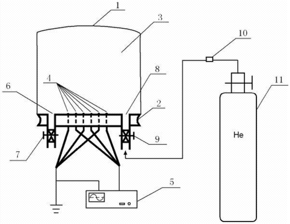
[0016] First, the material to be processed is directly placed on the plasma discharge area on the wire electrode 4, and a plastic electrical insulating film 1 with good air tightness and flexibility is covered on the edge of the electrical insulating dielectric plate 2 to be fixed and sealed to prevent air leakage. In this way, the reaction chamber 3 is formed; open the air extraction valve 7 to exhaust the air in the reaction chamber 3, either to flatten the plastic electrical insulating film 1 or use a manual air pump to assist in extracting all the gas, close the air extraction valve 7; open the flow meter 10 And the inlet valve 9, the gas supply source 11 slowly inflates the reaction chamber 3 through the flow meter 10 and the inlet valve 9 until the plastic electrical insulating film 1 is supported by the working carrier gas...


PUM


Abstract

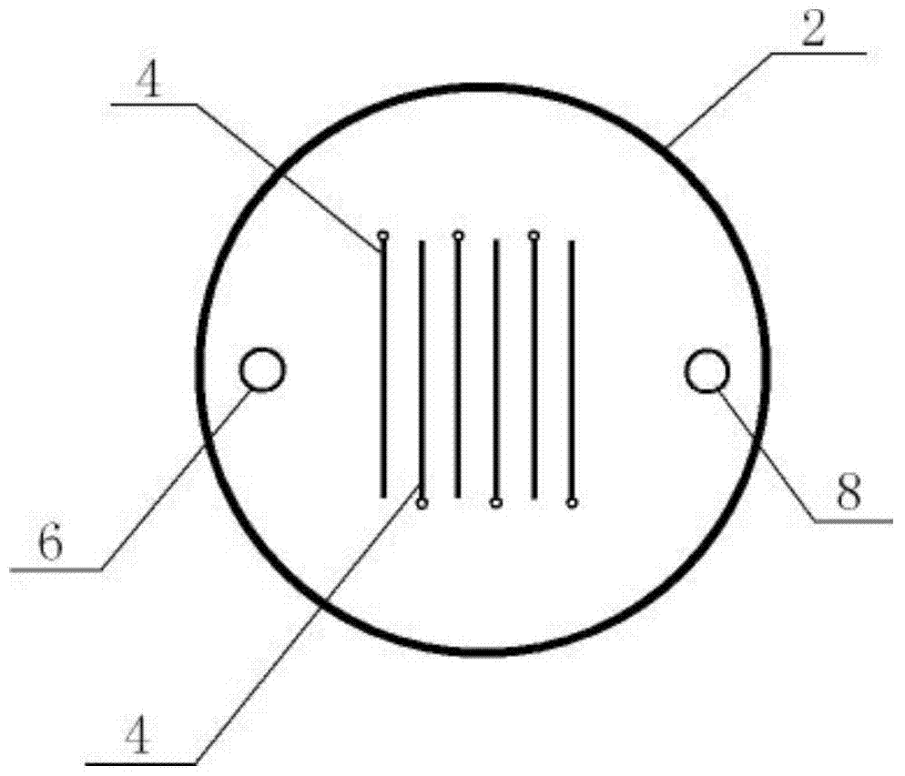
An atmospheric pressure surface discharge plasma device for surface modification of glass and polymer materials, belonging to the technical field of material surface treatment. It is characterized in that: a plastic electrically insulating film (1) is covered with an edge seal of an electrically insulating dielectric plate (2) to form a reaction chamber (3); the surface of the electrically insulating dielectric plate (2) facing the plastic electrically insulating film has a There are spaced, equal-length, parallel strip grooves, and line electrodes (4) are embedded in the strip grooves; adjacent line electrodes (4) are respectively connected at both ends of the strip groove through electrically insulating dielectric plates (2). The lead-out hole extends under the plate and is connected to the high and low voltage output ends of the high-voltage AC power supply (5); the processed material is directly placed in the plasma discharge area on the line electrode (4). The effect and benefit of the invention is to generate a large area of ​​uniform low-temperature plasma under normal pressure, increase the surface energy of the material in a short time, and improve the hydrophilicity. Provide a new processing technology for various industrial and medical applications.

Description

technical field [0001] The invention relates to a device for applying low-temperature plasma surface modification technology. In particular, the device for modifying the surface of glass and various organic macromolecular materials by cold plasma generated by atmospheric pressure surface discharge belongs to the technical field of material surface treatment. Background technique [0002] Low-temperature plasma technology is widely used in the surface treatment of materials. Among them, it is one of the important applications to act on the surface of materials to change the surface energy so as to improve the hydrophilicity. Hydrophilicity is one of the important properties of the material surface. Various water-based methods, such as wet chemical method, laser treatment, ultraviolet treatment and plasma treatment, etc. The low-temperature plasma surface treatment method has broad application prospects because it does not require chemicals, has no pollution to the environment...

Claims


Application Information

Patent Timeline
Patent Type & Authority Patents(China)
IPC IPC(8): C03C21/00
Inventor 李寿哲叶福莉
Owner DALIAN UNIV OF TECH
Learn More