
Porous pipe method large-diameter high-pressure jet grouting pile construction method

A technology of high-pressure rotary jetting pile and construction method, which is applied to sheet pile wall, foundation structure engineering, construction and other directions, can solve the problems of small pile diameter, low pile work efficiency, large soil squeeze effect, etc., and improve the pile forming efficiency. , saving engineering cost, and expanding the effect of pile diameter

Inactive Publication Date: 2015-04-29
上海开普天岩土科技集团有限公司 +1
View PDF6 Cites 7 Cited by
  • Summary
  • Abstract
  • Description
  • Claims
  • Application Information

AI Technical Summary

Problems solved by technology

[0003] The technical problem to be solved by the present invention is to provide a construction method for large-diameter high-pressure jet-jetted piles with porous pipe method (RJP construction method), which is used to solve the problems of low pile-forming efficiency, small pile diameter, and large soil-squeezing effect of conventional high-pressure jet-jet piles. Defects, the diameter of the high-pressure rotary grouting pile can reach 2.2~3m, and the overall pile-forming efficiency has increased by nearly 30% compared with the conventional high-pressure rotary grouting pile

Method used


Image

  • Porous pipe method large-diameter high-pressure jet grouting pile construction method
  • Porous pipe method large-diameter high-pressure jet grouting pile construction method

Examples


Embodiment Construction

[0018] The present invention will be further described below in conjunction with the accompanying drawings and embodiments.

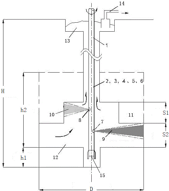
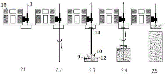
[0019] The invention provides a large-diameter high-pressure rotary grouting pile construction method (RJP construction method) with a porous pipe method. Through the reasonable arrangement and optimization of the jet flow of high-pressure water, compressed air, and ultra-high-pressure solidified liquid (cement slurry, etc.), the In the process of lifting piles, the high-pressure water flow and compressed air jet flow at the upper end and the ultra-high pressure solidified liquid jet flow and compressed air jet flow at the lower end are used for joint relay cutting, so that the pile diameter of the high-pressure rotary grouting pile can reach 2.2~3.5m, and the pile-forming efficiency is improved. Substantially improved. In conjunction with the accompanying drawings, the specific description is as follows:

[0020] Such as figure 1 , as shown in 2, in ...


PUM


Abstract

The invention relates to a porous pipe method large-diameter high-pressure jet grouting pile construction method. A high-pressure water conveying pipe, a high-pressure water compressed air conveying pipe and the like are arranged in a drill rod, the lower part of a drill bit is respectively provided with a high-pressure solidifying liquid and compressed air jet opening, a high-pressure water pipe jet opening and a compressed air water spraying opening, the positions of the high-pressure water pipe jet opening and the compressed air water spraying opening are positioned above the high-pressure solidifying liquid and compressed air jet opening, the bottom of the drill bit is provided with a high-pressure water jet opening, and the high-pressure water conveying pipe downwards jets water flow through the high-pressure water jet opening for cutting, so that the lower side of the drill pipe reaches the design pile bottom elevation, then, high-pressure water jet flow and compressed air jet flow are jetted from the high-pressure water pipe jet opening and the compressed air jet opening, high-pressure solidifying liquid and compressed air jet flow is jetted out from the high-pressure solidifying liquid and compressed air jet opening and is rotationally lifted along with the drill rod, and the peripheral soil bodies are subjected to secondary cutting, so that cement slurry and soil are stirred to be mixed into a pipe. Compared with an ordinary high-pressure jet grouting pile, the porous pipe method large-diameter high-pressure jet grouting pile has the advantage that the integral pile forming efficiency is improved by about 30 percent.

Description

technical field [0001] The present invention relates to a construction method of large-diameter ultra-high-pressure jet-jet piles (Rodin Jet Pile, hereinafter referred to as RJP construction method), which is applied to the reinforcement of foundation soil in construction engineering, the reinforcement of soil in the entrance and exit holes of shield tunnels, and the isolation of foundation pit engineering. Water curtains and other projects that require reinforcement and improvement of the soil. Background technique [0002] The conventional porous pipe method high-pressure rotary grouting pile used in previous projects uses high-pressure water and cement slurry to cut the soil at one time, and the low-pressure slurry is sprayed and mixed. The pile diameter is limited, generally 0.8-1.2m. Conventional porous pipe method high-pressure rotary grouting piles have low work efficiency, small pile diameter and great soil squeezing effect, and are likely to have adverse effects on ...

Claims


Application Information

Patent Timeline
Patent Type & Authority Applications(China)
IPC IPC(8): E02D5/46
CPCE02D5/46
Inventor 胡晓虎吴国明中西康晴
Owner 上海开普天岩土科技集团有限公司
Learn More