Engine ignition system and method

An ignition system and engine technology, applied in automatic control, automatic control, electrical automatic control, etc., can solve the problem that the ignition coil cannot realize alternate ignition of multiple coils, etc., and achieve the effect of improving the ignition efficiency, reducing the probability of misfire, and achieving sufficient combustion.

Inactive Publication Date: 2015-04-29
UNITED AUTOMOTIVE ELECTRONICS SYST
View PDF11 Cites 9 Cited by
  • Summary
  • Abstract
  • Description
  • Claims
  • Application Information

AI Technical Summary

Problems solved by technology

[0004] Existing ignition coils cannot realize the function of multi-coil alternate ignition

Method used


Image

  • Engine ignition system and method
  • Engine ignition system and method

Examples


Embodiment 1

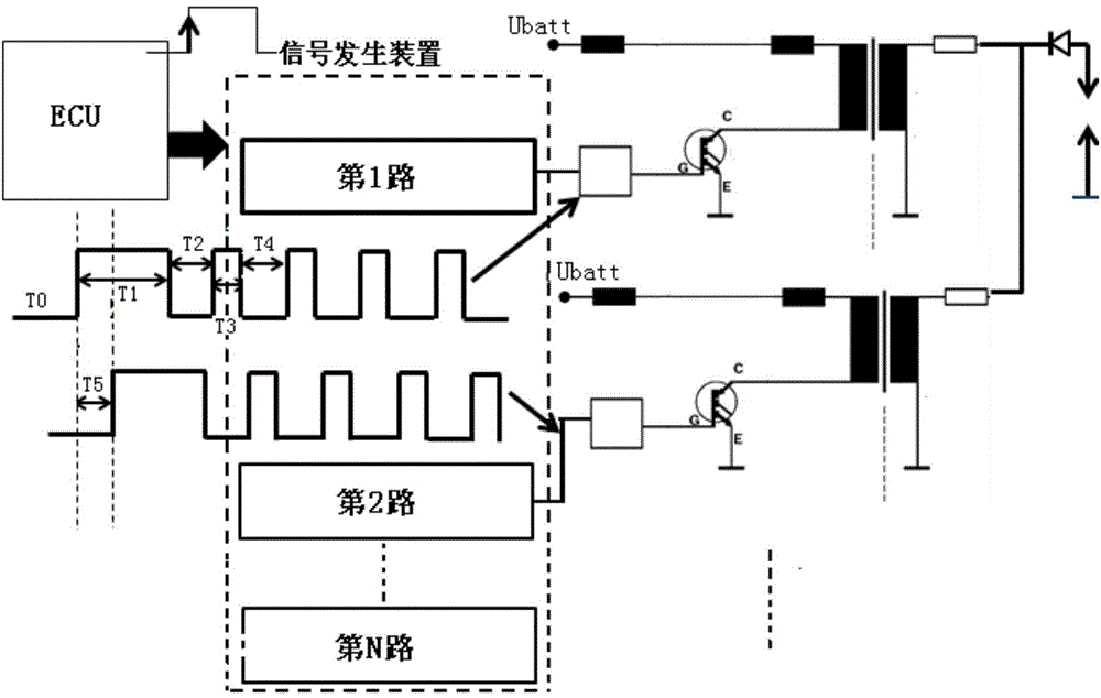
[0046] Engine ignition systems such as figure 2 As shown, including engine control unit ECU, signal generating device, and ignition coil, N ignition coils are installed in the same cylinder of the engine, and N is an integer greater than or equal to 2;

[0047] The N ignition coils, the primary coil winding loops are connected between the vehicle power supply Ubatt and the same ground, and the secondary coil winding loops are parallel connected between the spark plug high voltage ignition end of the cylinder and the ground;

[0048] The engine control unit ECU sends the ignition trigger signal of the cylinder to the signal generating device at the beginning of each ignition cycle of the cylinder of the engine;

[0049] The signal generating device, when receiving the ignition trigger signal of the cylinder sent by the engine control unit ECU, outputs the first to the Nth ignition coil control signals, respectively controlling the first to the Nth ignition coil control signals...

Embodiment 2

[0052] Based on the engine ignition system of Embodiment 1, switches are connected to the primary coil winding circuits of the N ignition coils;

[0053]The signal generating device, when receiving the ignition trigger signal of the cylinder sent by the engine control unit ECU, outputs N ignition coil control signals to respectively control the switching actions of the primary coil winding circuits of the N ignition coils of the cylinder, so that The N ignition coils of the cylinder start to ignite successively;

[0054] The N-way ignition coil control signals are composed of T0, T1, T2, T3, and T4 in sequence, and the number of continuous cycles of T3 and T4 is greater than or equal to 1;

[0055] T1>T3;

[0056] T0+T1+T2+(T3+T4)*h

[0057] T0 of the i-th ignition coil control signal is longer than T0 of the i-1th ignition coil control signal by T5.

[0058] Among them, T is the ignition cycle, h is a positive integer, T0 is the waiting time, T1 is the first charging ti...

Embodiment 3

[0063] Based on the engine ignition system of the second embodiment, the waiting time T0 of the first ignition coil control signal should be as short as possible, preferably 0, so as to respond to the ignition trigger signal in time.

[0064] Preferably, the ignition coil control signal is 1.8ms≤T1≤4ms, T2=T1 / 4, T3=T1 / 8, T4=T2, 0.1ms≤T5≤0.5ms.


PUM


Abstract

The invention discloses an engine ignition system. Multiple ignition coils are mounted in a same cylinder of an engine; a primary coil winding loop of each ignition coil is parallelly connected between a vehicular power supply and the ground, and a primary coil winding loop is parallelly connected between a high-voltage ignition end of a sparking plug of the cylinder and the ground; when receiving an ignition trigger signal, sent from an engine control unit, of the cylinder, a signal generator outputs multiple channels of ignition coil control signals for respectively controlling the ignition coils of the cylinder to start igniting successively. The invention further discloses an engine ignition method. By the engine ignition system and method, fire probability can be lowered, mixed gas in the cylinder is combusted more fully, igniting efficiency is increased, and power output of the engine is enhanced.

Description

technical field [0001] The invention relates to new energy vehicle technology, in particular to an engine ignition system and method. Background technique [0002] The structural principle diagram of the existing ignition coil is as follows: figure 1 As shown, it includes primary coil winding L1, secondary coil winding L2, and iron core. The primary coil winding L1 is connected to the vehicle power supply E, one end of the secondary coil winding L2 is grounded, and the other end is connected to the high-voltage ignition terminal of the spark plug P. The ignition coil is controlled by the engine control unit (ECU). When the ignition coil is working, the switch K of the primary coil winding circuit is closed, the vehicle power supply E charges the primary coil winding L1, and the electromagnetic energy is stored on the iron core in the magnetic circuit. When the current of the primary coil winding circuit reaches a certain value, the switch K of the primary coil winding circ...

Claims


Application Information

Patent Timeline
Patent Type & Authority Applications(China)
IPC IPC(8): F02P3/04F02P5/145
CPCF02P3/04F02P5/145
Inventor 茅一春孙晓庆周梦何宏宇
Owner UNITED AUTOMOTIVE ELECTRONICS SYST
Why Eureka
Try Eureka