Equipment power consumption acquiring device with various interfaces
A technology for collecting device and equipment power consumption, which is applied in the direction of measuring devices, instruments, measuring electronics, etc., can solve problems such as differences, affecting power consumption waveform analysis, and inability to test power consumption changes, etc., to achieve the goal of reducing volume and reducing production costs Effect
- Summary
- Abstract
- Description
- Claims
- Application Information
AI Technical Summary
Problems solved by technology
Method used
Image

Examples
Embodiment 1
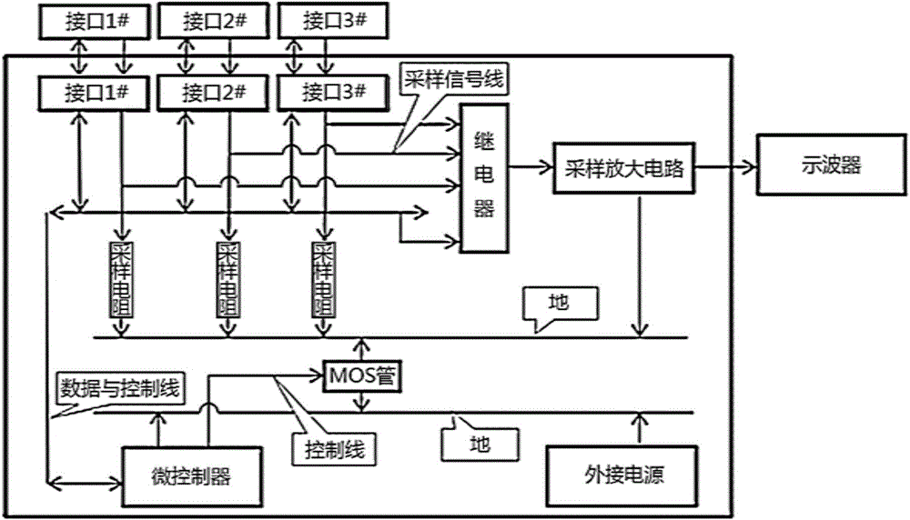
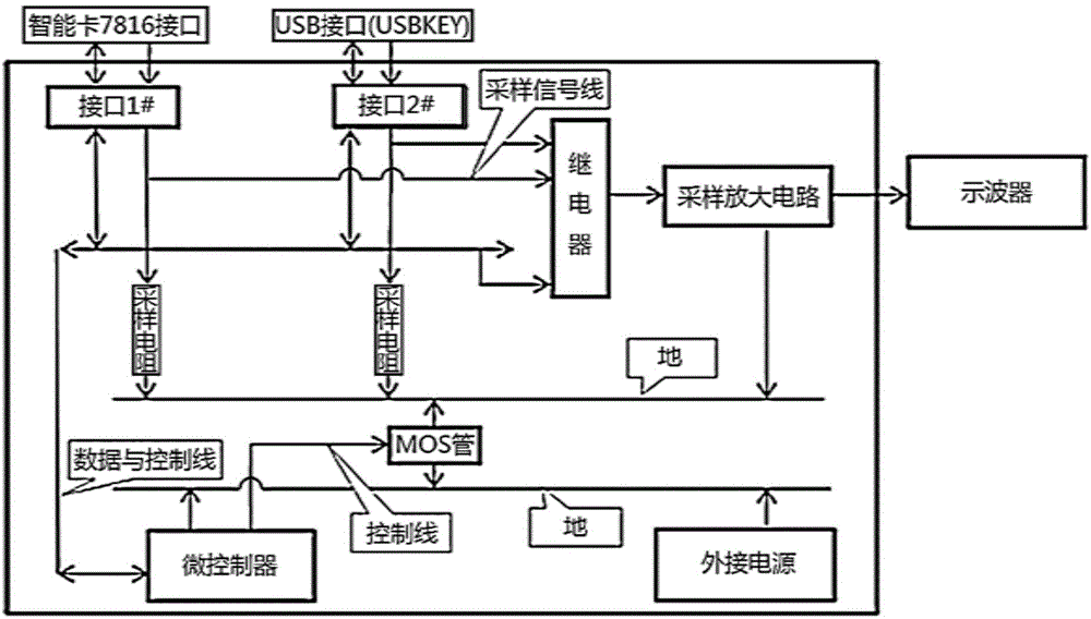
[0026] Such as figure 1 and image 3 As shown, this embodiment includes: a device power consumption acquisition device with multiple interfaces, including: several interfaces arranged on a circuit board connected to the sampling amplifier circuit through the sampling signal line, connected to the output terminal of the sampling amplifier circuit An oscilloscope and a microcontroller connected to the interface through a data control line, wherein: a relay is provided between the interface and the sampling amplifier circuit to output the analog signal information from the interface to the sampling amplifier circuit, and a GPIO port of the microcontroller It is connected to the gate of the isolation MOS transistor, and the GPIO port of the microcontroller controls the isolation MOS transistor to be turned on and off. The drain of the isolation MOS transistor is connected to the first ground line, and the source is connected to the second ground line.
[0027] The interface is us...
PUM
| Property | Measurement | Unit |
|---|---|---|
| Bandwidth | aaaaa | aaaaa |
Abstract
Description
Claims
Application Information
 - Generate Ideas
- Intellectual Property
- Life Sciences
- Materials
- Tech Scout
- Unparalleled Data Quality
- Higher Quality Content
- 60% Fewer Hallucinations
Browse by: Latest US Patents, China's latest patents, Technical Efficacy Thesaurus, Application Domain, Technology Topic, Popular Technical Reports.
© 2025 PatSnap. All rights reserved.Legal|Privacy policy|Modern Slavery Act Transparency Statement|Sitemap|About US| Contact US: help@patsnap.com