Network time-setting system and method for secondary equipment of electric power system

A secondary device and network time synchronization technology, applied in transmission systems, digital transmission systems, electrical components, etc., can solve the problems of high chip cost and limited number of independent ports of secondary devices, and achieve low cost, low cost, The effect of strong expansion performance

Active Publication Date: 2015-04-29
NARI TECH CO LTD +1
View PDF4 Cites 14 Cited by
  • Summary
  • Abstract
  • Description
  • Claims
  • Application Information

AI Technical Summary

Problems solved by technology

[0006] In order to solve the deficiencies in the prior art, the present invention provides a power system secondary equipment network time synchronization system and its time synch

Method used


Image

  • Network time-setting system and method for secondary equipment of electric power system
  • Network time-setting system and method for secondary equipment of electric power system

Examples


Embodiment Construction

[0024] The present invention will be further described below in conjunction with the accompanying drawings. The following examples are only used to illustrate the technical solution of the present invention more clearly, but not to limit the protection scope of the present invention.

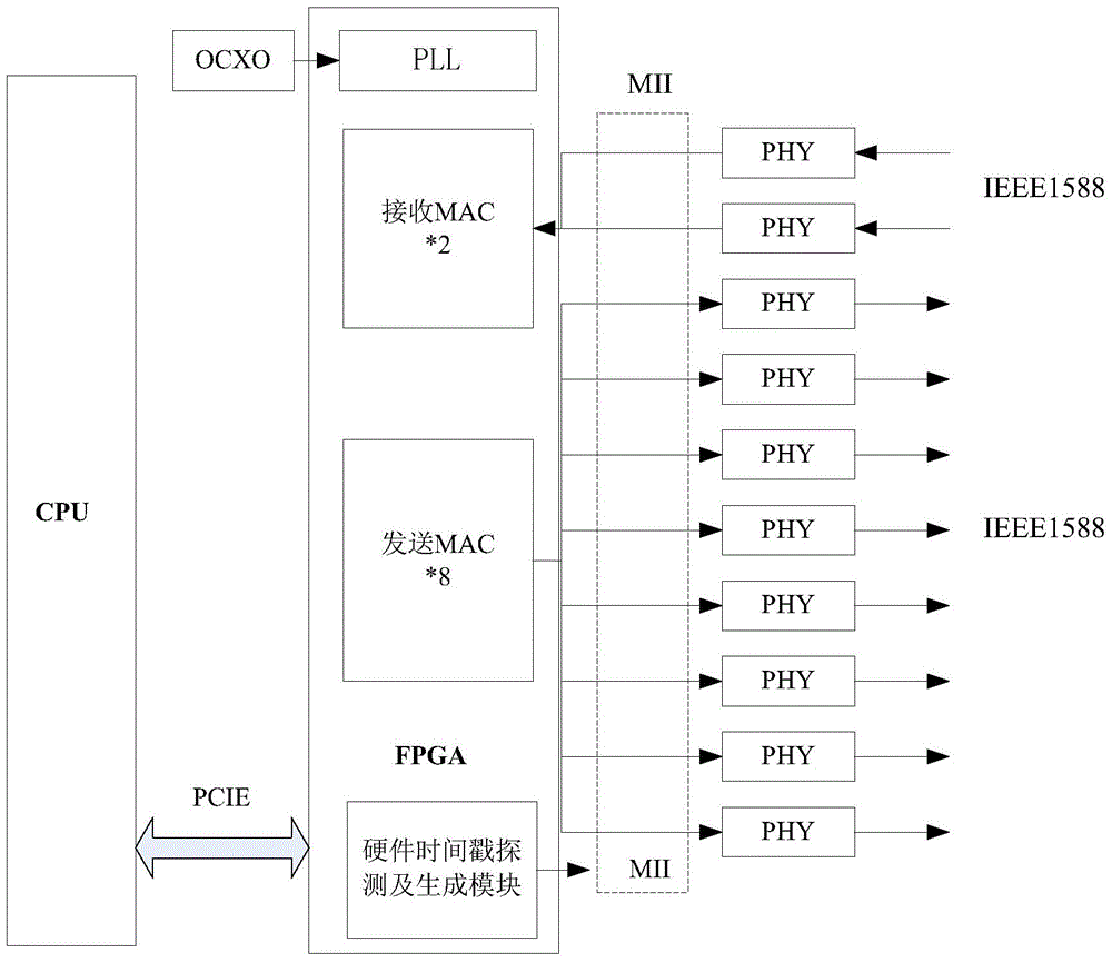
[0025] Such as figure 1 As shown, a power system secondary equipment network time synchronization system includes CPU, FPGA, physical layer network card chip PHY, constant temperature crystal oscillator OCXO; the CPU and FPGA are connected through the PCIE bus; the FPGA includes Ethernet implemented by the FPGA Media access controller MAC and hardware timestamp detection and generation module and phase-locked loop PLL; the MAC includes 8 sending MACs and 2 receiving MACs; the PHY and MAC are connected through the media independent interface MII; the OCXO and the PLL connected to provide a clock signal for the FPGA; the phase-locked loop PLL is used to eliminate the distortion and delay of the O...


PUM


Abstract

The invention discloses a network time-setting system and method for secondary equipment of an electric power system. The network time-setting system is characterized by comprising a CPU (central processing unit), an FPGA (field programmable gate array), a physical layer network card chip PHY and an oven controlled crystal oscillator OCXO, wherein the CPU is connected with the FPGA through a PCIE (peripheral component interface express) bus; the FPGA comprises Ethernet medium access controllers (MAC) which are realized through the FPGA, a hardware time stamp detecting and generating module and a phase locking loop (PLL). The time-setting method comprises the following steps: inputting setting time through a network, filtering messages, improving the time -setting synchronizing precision of the messages, adding hardware time stamps to the messages through the FPGA, synchronizing network setting-time, and outputting network setting-time. The network time-setting system disclosed by the invention uses the FPGA as a core, and under the condition that a hardware structure is not changed, multichannel high-precision network time setting can be realized at a relatively low cost; besides, through the phase locking loop (PLL) and a technique of additionally stamping the hardware time stamps on an MII (media independent interface) layer, the network time-setting precision can also be greatly improved, and the expansion performance is good.

Description

technical field [0001] The invention relates to a time synchronization system and method for a secondary equipment network of a power system, belonging to the technical field of power automation. Background technique [0002] In smart substations, the application of synchronous time synchronization of secondary equipment begins to transition from pulse logic time synchronization to digital network time synchronization, which is an inevitable requirement for full digitalization of smart substations. Since the secondary equipment such as the merging unit and PMU (Phasor Measurement Unit) in the smart substation has high requirements for timing accuracy and stability, the remaining secondary equipment has high requirements for timing accuracy in order to improve sampling accuracy and facilitate accident analysis. Higher and higher. Therefore, high-precision network time synchronization has become a basic function of secondary equipment in power systems. [0003] At present, t...

Claims


Application Information

Patent Timeline
IPC IPC(8): H04L7/00H04L7/033
Inventor 汪鹤沈健侯明国熊健韩伟檀永相蓉刘东升
Owner NARI TECH CO LTD
Why Eureka
Try Eureka