Intelligent cooler control system and method for transformer

A control system and control method technology, applied in the field of transformer control, can solve problems affecting the safe operation of transformers, reducing cooling efficiency, cooling system blockage, etc., and achieve the goals of easy processing and corresponding output, saving operation and maintenance costs, and prolonging service life Effect

Active Publication Date: 2015-05-06
CHINA XD ELECTRIC CO LTD
View PDF5 Cites 13 Cited by
  • Summary
  • Abstract
  • Description
  • Claims
  • Application Information

AI Technical Summary

Problems solved by technology

[0003] With the development of smart grid, the requirements for the operation of transformers and components are getting higher and higher, especially in some special environments, transformers are required to be able to operate reliably and be easy to maintain; The wind side is easily blocked by dust, poplar and other debris, which reduces the cooling efficiency and affects the safe operation of the transformer. The traditional method is manual regular inspection and manual cleaning. The original cooling system cannot meet the requirements of automation, digitalization and information transmission for intelligent transformers. Cooler is an important protection device for transformers, especially large transformers have more and more requirements for coolers, the existing cooling system can no longer meet the needs of use, resulting in low heat dissipation efficiency and poor matching

Method used


Image

  • Intelligent cooler control system and method for transformer
  • Intelligent cooler control system and method for transformer

Examples


Embodiment Construction

[0037] The present invention will be further described in detail below in conjunction with the accompanying drawings, which are explanations rather than limitations of the present invention.

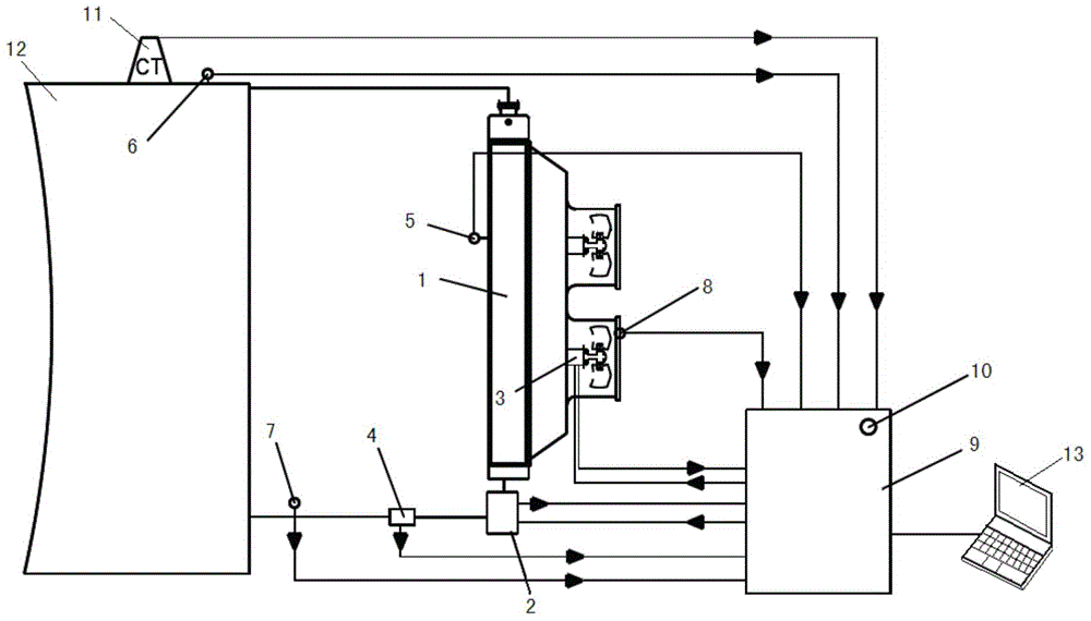
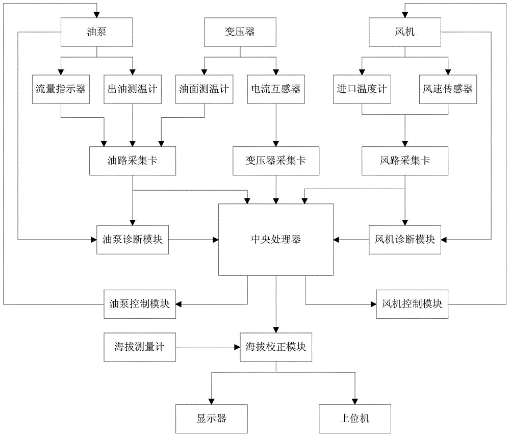
[0038] The present invention is an intelligent cooler control system for transformers, such as figure 1 As shown, it includes a current transformer 11 and an oil level thermometer 6 arranged on the transformer 12, an oil outlet thermometer 7 and a flow indicator 4 arranged on the output pipeline of the oil pump 2 in the cooler 1, and is arranged on the The inlet thermometer 5 of the fan 3 inlet in the cooler 1, the wind speed sensor 8 arranged at the outlet of the fan 3 in the cooler 1, and the control box 9 of the control circuit; the control circuit includes a data acquisition card connected in sequence, and the central processing controller and control module; the central processor is used to send control instructions to the control module according to the data obtained by the data ac...


PUM


Abstract

The invention provides an intelligent cooler control system for a transformer. The intelligent cooler control system comprises a current transformer, an oil level temperature measuring meter, an oil outlet temperature measuring meter, a flow indicator, an inlet thermometer, a wind speed sensor and a control box, wherein the current transformer and the oil level temperature measuring meter are arranged on the transformer, the oil outlet temperature measuring meter and the flow indicator are arranged on an output pipeline of an oil pump which is arranged in a cooler, the inlet thermometer is arranged at the position of a fan inlet which is arranged in the cooler, the wind speed sensor is arranged at the position of a fan outlet which is arranged in the cooler, and the control box is provided with a control circuit. An intelligent cooler control method comprises step 1, initializing parameter settings and collecting control parameters; step 2, obtaining the actual cooling capacity of a cooling system and the actual losses of the transformer through calculation according to intrinsic parameters of the transformer and the collected control parameters; step 3, performing comparison on the actual cooling capacity Py of the cooler and the actual losses P of the transformer and controlling the oil pump of the cooler and or a fan according to a comparison result; step 4, repeating the step 2 and the step 3 according to the intrinsic parameters of the transformer and the timely-collected control parameters until the oil pump and the fan reach the operation state when Py is equal to P in the step 3.

Description

technical field [0001] The invention relates to the technical field of transformer control, in particular to an intelligent cooler control system for a transformer and a control method thereof. Background technique [0002] The cooler is used to cool the electrical equipment, and it is used on the transformer to reduce the temperature of the hot oil inside the transformer oil tank. When the oil-immersed transformer is in normal operation, the oil in the oil tank is heated due to the heat generated by the coil, which makes the internal temperature of the oil tank rise. If this temperature is not released in time, it will affect the safe operation of the transformer. The installation of heat dissipation equipment is to reduce the temperature in the oil tank when the temperature in the oil tank rises, so as to ensure the safe operation of the transformer. [0003] With the development of smart grid, the requirements for the operation of transformers and components are getting...

Claims


Application Information

Patent Timeline
Patent Type & Authority Applications(China)
IPC IPC(8): G05D23/19
Inventor 符胜利孙颋杨轶江王文翰谢继红马红军刘博雷超
Owner CHINA XD ELECTRIC CO LTD
Why Eureka
Try Eureka