
Tailor welded blank integral drawing forming device and method for large-scale curved surface part

A technology for tailor-welded blanks and curved parts, which is applied in the field of tailor-welded blank integral forming devices, can solve the problems of inability to form large-scale tailor-welded blank curved parts, and weld cracks, etc. The effect of strong pressure capacity and high reliability

Active Publication Date: 2015-05-13
HARBIN INST OF TECH
View PDF6 Cites 20 Cited by
  • Summary
  • Abstract
  • Description
  • Claims
  • Application Information

AI Technical Summary

Problems solved by technology

[0005] Aiming at the problem that weld seams are cracked during the drawing process of tailor-welded blanks and large-scale tailor-welded blanks cannot be formed, the present invention provides a tailor-welded blank drawing method and device for large-scale curved surfaces to avoid deep-drawing The cracking of the weld seam during the process and the formation of large tailor-welded blank surface parts

Method used


Image

  • Tailor welded blank integral drawing forming device and method for large-scale curved surface part
  • Tailor welded blank integral drawing forming device and method for large-scale curved surface part
  • Tailor welded blank integral drawing forming device and method for large-scale curved surface part

Examples


specific Embodiment approach 1

[0028] Specific implementation mode one: as Figures 1 to 7 As shown, the overall drawing and forming device for tailor-welded blanks of large curved surface parts in this embodiment includes a punch 1, a blank holder 2, a die 3, and a liquid-filled chamber 4; the die 3 is placed between the liquid-filled chamber 4 The upper and the two are sealed and connected by the sealing ring 6, and the lower plane of the die 3 is fixedly connected with the upper plane of the liquid-filled chamber 4; the blank holder 2 is arranged above the die 3; The mold 3 moves up and down; the liquid filling chamber 4 is provided with a liquid injection hole 4-1 connected with the medium chamber 5, and the liquid injection hole 4-1 is used to connect with the hydraulic system; the blank holder 2 and the die 3 are used to place Sheet 7, the sheet 7 refers to tailor-welded blanks of non-equal thickness;

[0029] like Figure 2-5 On the surface of the punch 1, there is a punch groove 1-1 that matches t...

specific Embodiment approach 2

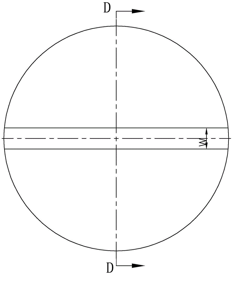
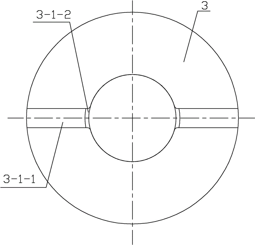
[0034]Specific implementation mode two: as Figure 8 and 9 As shown, in the tailor-welded blank overall drawing forming device for large curved surface parts described in this embodiment, there are only holes on the upper surface and inner hole of the die 3 that match the shape of the thick-walled area where the weld seam of the sheet metal is located. Die groove 3-1 is used to restrict the deformation of the thick-walled area perpendicular to the direction of the welding seam. The concave mold groove 3-1 is a two-part groove arranged opposite to the mirror image along the axis of the concave mold 3, and each part of the groove includes a concave mold upper surface groove 3-1- 1 and the concave mold inner hole groove 3-1-2 arranged on the inner hole wall of the concave mold and equal to the inner hole, and the groove 3-1-1 on the upper surface of the concave mold and the inner hole groove 3 of the concave mold -1-2 is smoothly transitioned and connected at the intersection; ...

specific Embodiment approach 3

[0037] Specific embodiment 3: The steps of the overall drawing and forming method of tailor-welded blanks for large curved surface parts using the forming device of specific embodiment 1 are as follows:

[0038] Step 1. The liquid filling hole of the liquid filling chamber is connected to the hydraulic system: first, the liquid injection hole 4-1 on the liquid filling chamber 4 is connected to the hydraulic system, and then the fluid medium is injected into the medium chamber 5;

[0039] Step 2, then place a non-equal-thick sheet material 7 on the upper surface of the die 3, and the sheet material 7 has a side with a stepped surface upward;

[0040] Step 3. The blankholder moves downward and applies blankholder force, and the groove of the blankholder coincides with the thick-walled area of ​​the sheet:

[0041] The blank holder 2 is controlled to move downward by the blank holder cylinder of the hydraulic press, the groove of the blank holder 2 matches the sheet material 7, t...


PUM


Abstract

The invention discloses a tailor welded blank integral drawing forming device and a method for a large-scale curved surface part, relates to the tailor welded blank integral forming device and method, and the problem that in the prior art, fractures exist in tailor welded blank integral forming is solved. The tailor welded blank integral drawing forming device comprises a male die, a blank holder, a female die and a liquid filling chamber; the portion between the blank holder and the female die is used for containing an unequal thickness tailor welded blank; the profile of the male die is provided with a male die groove which is consistent with the shape of a thick wall area where a sheet metal weld joint is located, blank holder grooves which are consistent with the shape of the thick wall area where the sheet metal weld joint is located are formed in an inner hole of the blank holder and the lower surface of the blank holder simultaneously, and the male die groove and the blank holder grooves are used for preventing the portion, perpendicular to the direction of the weld joint, of the thick wall area from deforming; or female die grooves which are consistent with the shape of the thick wall area where the sheet metal weld joint is located are formed in the upper surface of the female die and an inner hole of the female die and used for preventing the portion, perpendicular to the direction of the weld joint, of the thick wall area from deforming. The invention further provides a tailor welded blank integral drawing forming method of the large-scale curved surface part through using the tailor welded blank integral drawing forming device. The tailor welded blank integral drawing forming device and the method for the large-scale curved surface part are used for filling liquid, drawing and forming for the unequal thickness and symmetrical tailor welded blank through adopting uniform strength bearing design.

Description

technical field [0001] The invention relates to an overall forming device and method for tailor welded blanks. Background technique [0002] Curved parts such as heads are widely used in petrochemical, aerospace and other fields. The diameter is generally more than 2000mm, and it is a large curved plate part. The existing manufacturing method is to manufacture the melon petal parts by deep drawing or drawing method, and then the melon petals are stitched and welded into spherical parts. Since such parts are usually combined with the barrel section to form a pressure vessel, the reliability and load-bearing capacity of the weld are highly required. At present, the existing forming method of block forming and then welding has the disadvantages of many weld seams, large degree of restraint, forced assembly and welding deformation are prone to high levels of welding residual stress, and low reliability under pressure conditions. At present, there is an urgent need to solve the...

Claims


Application Information

Patent Timeline
IPC IPC(8): B21D26/021B21D26/031
Inventor 徐永超苑世剑刘伟
Owner HARBIN INST OF TECH
Learn More