Testing device for radiation luminance gain of ultraviolet image intensifier

A technology of image intensifier and radiance, which is applied in the field of ultraviolet image intensifier performance testing, to achieve the effect of simple structure, easy processing and simple overall structure

Inactive Publication Date: 2015-05-13
NANJING UNIV OF SCI & TECH
View PDF5 Cites 18 Cited by
  • Summary
  • Abstract
  • Description
  • Claims
  • Application Information

AI Technical Summary

Problems solved by technology

However, there is no device for testing the rad

Method used


Image

  • Testing device for radiation luminance gain of ultraviolet image intensifier
  • Testing device for radiation luminance gain of ultraviolet image intensifier
  • Testing device for radiation luminance gain of ultraviolet image intensifier

Examples


Embodiment 1

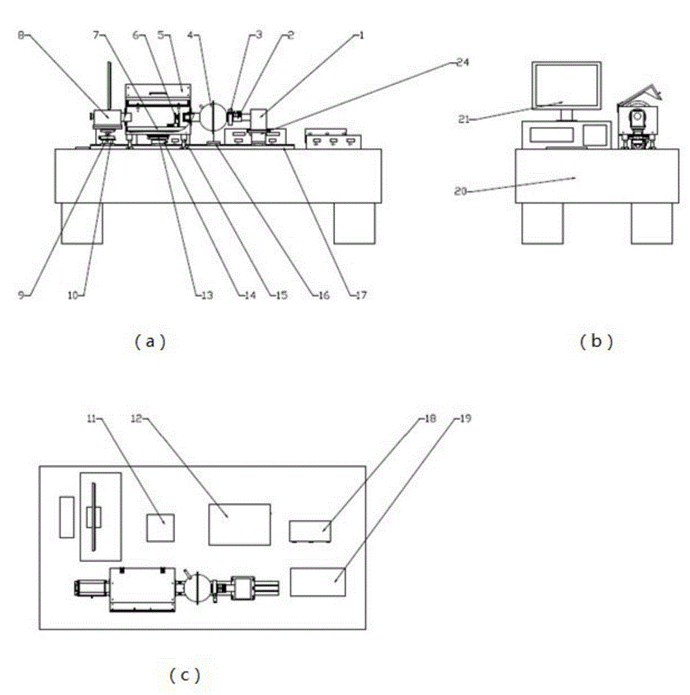
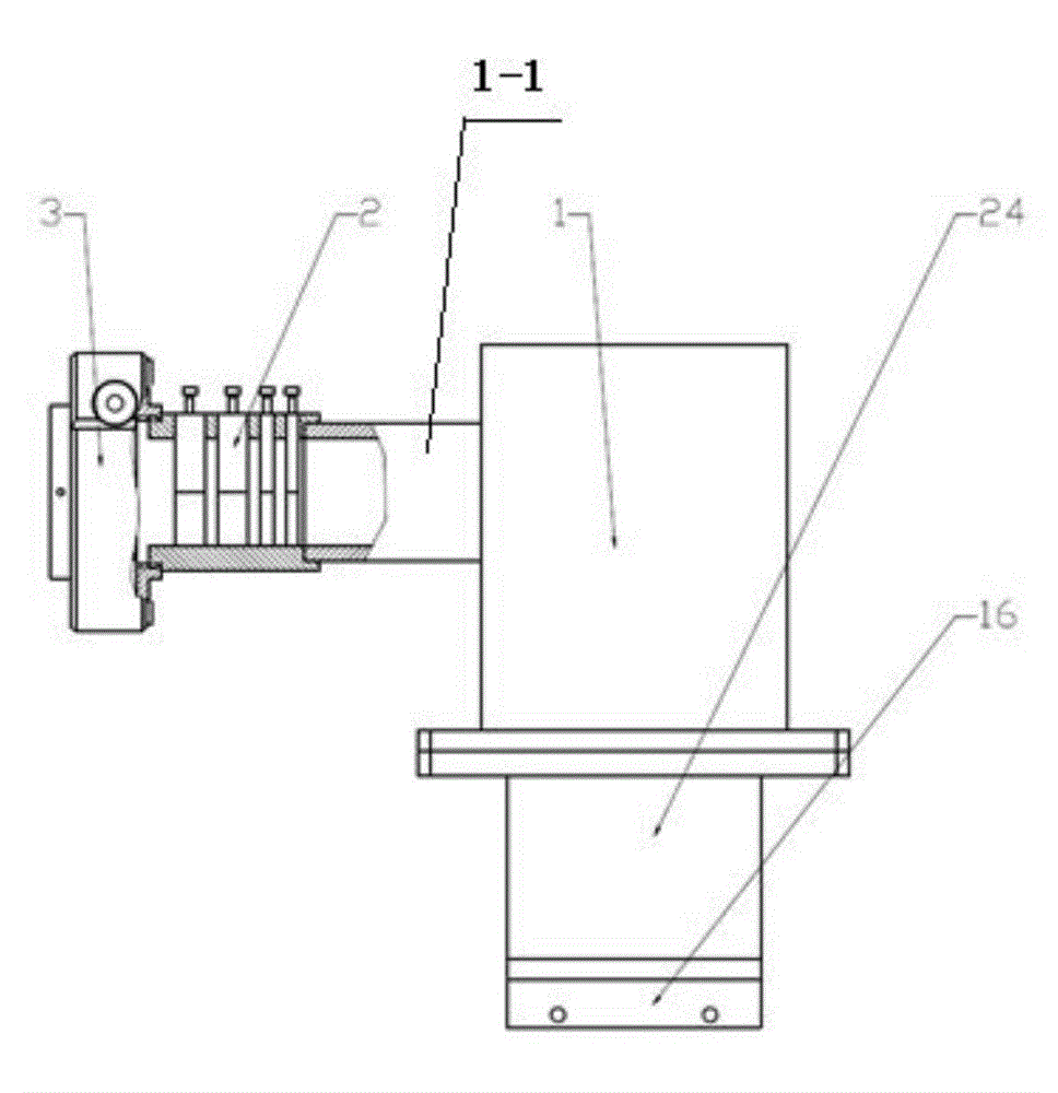
[0042] combine figure 2 , The light source device includes an ultraviolet light source 1, an optical filter 2, and an aperture adjustment device 3. The ultraviolet light source 1 is provided with an ultraviolet light generator, and the ultraviolet light source 1 is provided with an extension cylinder 1-1.

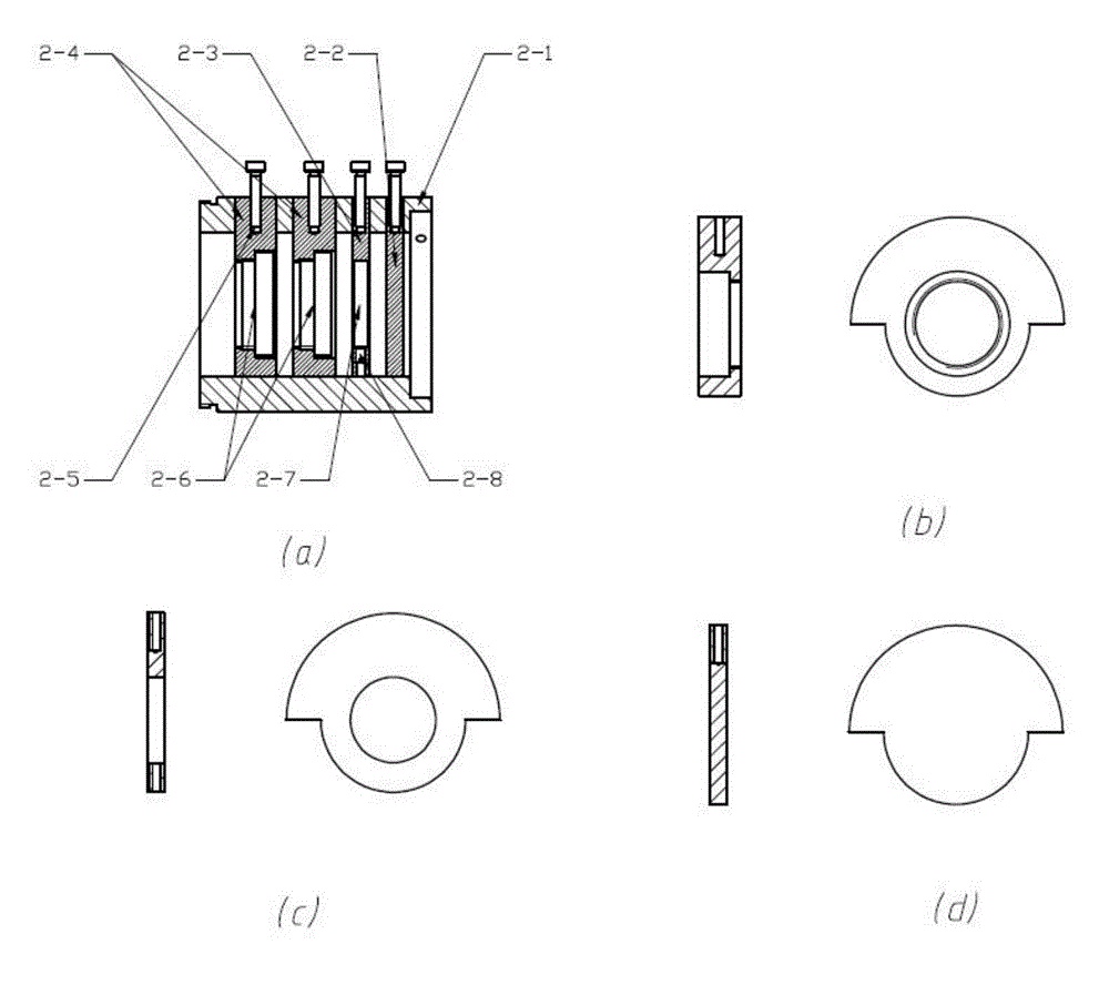
[0043] combine image 3 , the optical filter 2 includes a support cylinder 2-1, a blind sheet 2-2, an optical filter insertion sheet 2-3, an attenuation sheet insertion sheet 2-4, an attenuation sheet 2-6, and an optical filter sheet 2-7. The area of ​​the filter insert 2-3 and the attenuation plate insert 2-4 is greater than the cross-sectional area of ​​the through hole of the support tube 2-1.

[0044] One end of the support cylinder 2-1 is inserted into the extension cylinder 1-1 to connect with the ultraviolet light source 1, and the other end is connected with the aperture adjustment device 3; the outer wall of the support cylinder 2-1 is vertical from the end near ...

Embodiment 2

[0054] combine Figure 5 , The integrating sphere 4 includes a right hemisphere 4-1 and a left hemisphere 4-2 fixed together. The right hemisphere 4-1 is provided with a light inlet cylinder 4-6, and the light inlet cylinder 4-6 is inserted into a through hole on the rear surface of the tray 3-2. The left hemisphere 4-2 is provided with a cylindrical extension tube 4-3, and the rear end of the extension tube 4-3 is provided with a cylindrical light output tube 4-4, and the exit of the light output tube 4-4 is provided with a diaphragm 4-5; The outer diameter of the light emitting tube 4-4 is greater than the outer diameter of the extension tube 4-3; the light emitting tube 4-4 goes deep into the test dark box 5. The inner walls of the right hemisphere 4-1 and the left hemisphere 4-2 are coated with barium sulfate mixed with colloidal adhesive, and after multiple reflections of the inner wall coating, a uniform illuminance is formed on the inner wall, and uniform light is form...

Embodiment 3

[0057] combine Figure 8 , the tested image intensifier fixture device is provided in the test dark box 5, and the tested image intensifier fixture device includes a bare pipe fixture 6 and a fixture slide plate 7.

[0058] The fixture sliding plate 7 is arranged on the bottom surface of the test dark box 5 , and the fixture slider 22 is arranged on the upper bottom thereof, and the fixture slider 22 slides along the extending direction of the guide rail 17 .

[0059] The bare pipe clamp 6 includes a front plate 6-1, a rear plate 6-2, a clamp slider 6-3, a spring 6-4, a base 6-5, a thick slide bar 6-6, and a thin slide bar 6-7.

[0060] The base 6-5 is arranged on the fixture slide plate 7, and the bottom surface of the base 6-5 is provided with a cuboid slide plate groove;

[0061] The fixture slider 6-3 is located in the groove of the base 6-5;

[0062] The front plate 6-1 of the bare pipe fixture 6 is fixed on the front end of the upper bottom surface of the base 6-5; the...


PUM

PropertyMeasurementUnit
Diameteraaaaaaaaaa
The inside diameter ofaaaaaaaaaa
Wavelengthaaaaaaaaaa

Abstract

The invention provides a testing device for the radiation luminance gain of an ultraviolet image intensifier. The testing device comprises an optical platform and a guide rail arranged on the optical platform, wherein four sliding blocks are arranged on the guide rail, and a light source device, an integrating sphere, a testing dark box and a photometer are arranged on the four sliding blocks in sequence. The light source device emits ultraviolet light, the integrating sphere converts the ultraviolet light into uniform light, the tested image intensifier is arranged in the testing dark box, the uniform light irradiates the cathode surface of the image intensifier, and the photometer measures luminance of a fluorescent screen of the image intensifier; the set heights of the integrating sphere, the testing dark box and the photometer enable light in the testing dark box to be located in a straight line; the tested image intensifier is powered by an external power source. The testing device can detect the radiation luminance gain of the ultraviolet image intensifier, is simple in structure, and has significance on providing technical support for development of a novel detection imaging technology and offering help to the fields of power system detection, the space science and environmental protection research.

Description

technical field [0001] The invention relates to the technical field of performance testing of ultraviolet image intensifiers, in particular to a radiation brightness gain testing device of ultraviolet image intensifiers. Background technique [0002] Ultraviolet (UV) spectral imaging detection technology is a new detection imaging technology developed by European and American countries for military purposes. Its characteristic is to observe and detect "solar-blind" (240-280nm) ultraviolet light signals, and convert ultraviolet image signals into visible light image signals for observation and measurement. Using this technology, many physical, chemical, and biological phenomena that cannot be observed with traditional optical instruments can be observed; and because it works in the "solar blind" band, its work is not disturbed by sunlight, that is, the instrument using this technology can Working under sunlight, the image is clear, reliable and easy to use. Developed countr...

Claims


Application Information

Patent Timeline
IPC IPC(8): G01M11/00G01R31/26
Inventor 邱亚峰钱芸生刘涛刘健
Owner NANJING UNIV OF SCI & TECH
Why Eureka
Try Eureka