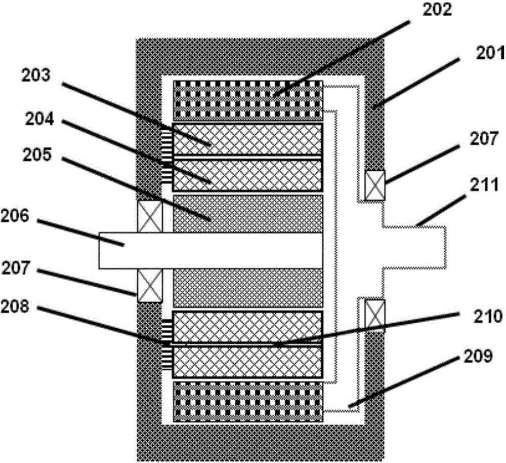
[0037] see image 3 , which is an embodiment of the present application for a synchronous motor for an extended-range electric vehicle. The casing 201 encloses an inner cavity, and an outer rotor 202 , a first stator 203 , a second stator 204 and an inner rotor 205 are arranged in the inner cavity. The housing is, for example, made of cast aluminum. The first stator 203 and the second stator 204 are fixed on the housing 201 by fixing bolts 208 . The first stator 203 surrounds the second stator 204 with a certain gap between them, and the cooling water channel 210 is disposed in the gap. The outer rotor is rotatably disposed on the periphery of the first stator 203, which is a permanent magnet component. The inner rotor 205 is rotatably provided inside the second stator 204, which is an electrically exciting part. The motor input shaft 206 is rotatably fixed to the casing 201 through the bearing 207 , and the motor output shaft 211 is also rotatably fixed to the casing 201 through the bearing 207 . The bearing 207 is, for example, a deep groove ball bearing. The Hall sensor 209 is arranged on the outer rotor 202, or the motor output shaft 211, or the combination of the two. Preferably, a plurality of Hall sensors 209 , such as more than three, are placed in the housing 201 to improve detection accuracy.
[0038] Wherein, the motor input shaft 206, the inner rotor 205 and the second stator 204 mainly constitute a generator, which is an electrically excited synchronous motor. The second stator 204 further includes a second stator core and an inner winding. The motor input shaft 206 is directly connected to the output shaft (crankshaft) of the internal combustion engine. Due to the small diameter of the generator, the use of electric excitation design can effectively avoid the defect of low utilization rate of permanent magnet steel. In addition, in the extended-range electric vehicle, the generator only works when the power of the high-voltage battery is insufficient, and the operating point is relatively single, so it is preferable to adopt a low-cost electric excitation design.
[0039] Wherein, the first stator 203, the outer rotor 202 and the motor output shaft 211 mainly constitute the drive motor, which is a built-in permanent magnet synchronous motor. The first stator 203 further includes a first stator core and an outer winding. The motor output shaft 211 is connected with the speed reducer.
[0040]Further, an oil seal design is adopted between the casing 201 , the motor input shaft 206 and the bearing 207 . Similarly, an oil seal design is also adopted between the housing 201 , the motor output shaft 211 and the bearing 207 . In this way, the lubricating oil or cooling oil is sealed inside the entire synchronous motor, and the oil is splashed when the inner and outer rotors rotate, which can cool the inner and outer rotors and improve the continuous performance of the motor.
[0041] see Figure 4 and Figure 5 , the power system of the extended-range electric vehicle of this application includes an internal combustion engine 101, a synchronous motor 200 (such as image 3 shown), dual motor controller 104, high voltage battery 105, reducer 106, fuel tank 107. The synchronous motor 200 includes a generator module and a driving motor module. The dual motor controller 104 can also be changed to two independent motor controllers.
[0042] The range-extending electric vehicle has two working modes, which are pure electric mode and range-extending mode.
[0043] see Figure 4 , when the power of the high-voltage battery 105 is high, the dual-motor controller 104 obtains energy from the high-voltage battery 105, outputs power through the driving motor module in the synchronous motor 200, and transmits power to the driving wheels through the reducer 106 to drive the vehicle forward . This is pure electric mode. At this time, the internal combustion engine 101 is turned off, the amount of fuel in the fuel tank 107 remains unchanged, and the generator module in the synchronous motor 200 does not work.
[0044] see Figure 5 , when the power of the high-voltage battery 105 is low, the generator module in the synchronous motor 200 first obtains energy from the high-voltage battery 105 through the dual-motor controller 104, and outputs a short-term high torque (for example greater than 150Nm) to start the internal combustion engine 101. Then the internal combustion engine 101 obtains energy by burning the fuel in the fuel tank 107 , and drives the generator module in the synchronous motor 200 to run. The generator module in the synchronous motor 200 charges the high voltage battery 105 through the dual motor controller 104 . The dual-motor controller 104 still obtains energy from the high-voltage battery 105, outputs power through the driving motor module in the synchronous motor 200, and transmits power to the driving wheels through the reducer 106 to drive the vehicle forward. In this way, the continuous operation of the driving motor 103 can be maintained. This is the extended range mode.
[0045] For an extended-range electric vehicle, the output shaft of the internal combustion engine 101 is not directly involved in driving the vehicle, but is only used for charging when the high-voltage battery 105 is insufficient. Therefore, there is no torque fluctuation when switching from the pure electric mode to the extended range mode, and the ride comfort of the whole vehicle is guaranteed.
[0046] The synchronous motor used for the extended-range electric vehicle in this application has the following advantages:
[0047] First, the power of the generator is small, and the inner rotor motor is used; the power of the driving motor is large, and the outer rotor motor is used. The three-dimensional structure in which the drive motor surrounds the generator enables the axial length of the entire synchronous motor to be effectively controlled. For the current mainstream power system with transverse internal combustion engine and transverse reducer, the requirements for the transverse space in the engine compartment are reduced, so the engine including the generator and drive motor can be arranged in the limited space in the front compartment of the vehicle. Synchronous motor, compact structure, high layout flexibility. In this way, the rear cabin of the whole vehicle can be used to place all the high-voltage battery packs, so that the chassis and suspension of the whole vehicle can be changed less.
[0048] Second, a cooling water channel 210 is provided in the gap between the stator of the driving motor (the first stator 203 ) and the stator of the generator (the second stator 204 ). In this way, water cooling can be used to dissipate heat from the two, which can significantly reduce the temperature of the two stators, and improve the peak output capability and duration of the drive motor and generator. At the same time, the oil cooling design is retained, and the rotors of the driving motor and generator are cooled by splashing, which further improves the continuous output power of the driving motor and generator.
[0049] Third, due to the barrier of the cooling water channel 210, the mutual coupling and interference of the flux linkages of the two motor windings are avoided. Since the generator in the synchronous motor 200 is decoupled from the drive motor, the output load of the internal combustion engine 101 is relatively small, and the operating point is relatively single (such as 80Nm, 2500rpm), so a small displacement internal combustion engine (such as a three-cylinder engine) can be used to Reduce fuel consumption and emissions to a greater extent.
[0050] Fourth, the generator and the drive motor can share a stator mold, which improves the material utilization rate of the silicon steel sheet.
[0051] Fifth, the generator adopts an electric excitation synchronous motor without rare-earth permanent magnets, which saves costs.
[0052] Sixth, the drive motor adopts the design of the built-in magnetic steel of the outer rotor. Compared with the surface-mounted design, its vibration resistance level is higher. Withstand greater centrifugal force. The outer diameter of the driving motor is larger than that of the generator, and the outer rotor design can arrange more magnetic steels in the circumference of the outer rotor to increase the torque/power density of the driving motor.
[0053] Seventh, the hall sensor 209 is used to detect the real-time position of the outer rotor 202 in the outer rotor motor. For example, the design of one ring gear and three sensors is adopted. Compared with the outer rotor resolver, the technology of the Hall sensor is mature, easier to implement, and lower in cost.
[0054] The above are only preferred embodiments of the present application, and are not intended to limit the present application. For those skilled in the art, various modifications and changes may occur in this application. Any modifications, equivalent replacements, improvements, etc. made within the spirit and principles of this application shall be included within the protection scope of this application.