Processing method for automatic dosing system

A technology of automatic dosing and processing methods, which is applied to metal processing equipment, metal processing machinery parts, maintenance and safety accessories, etc., and can solve problems such as time-consuming and cost-consuming, reduced ability of cooling and flushing cutting, poor work efficiency, etc. , to achieve the effect of saving man-hours and costs and maintaining concentration

Inactive Publication Date: 2015-05-20
DESIGNING FUTURE TECH
View PDF5 Cites 3 Cited by
  • Summary
  • Abstract
  • Description
  • Claims
  • Application Information

AI Technical Summary

Problems solved by technology

[0004] Furthermore, cutting fluid can be mainly divided into three types: oily cutting oil, water-soluble cutting oil, and synthetic cutting fluid. For different workpiece materials, appropriate cutting fluid should be used in the cutting process. Among them, water-soluble cutting oil is made of It is made of mineral oil, emulsifier, antirust additive, preservative and defoamer and other additives, and has a wide range of cutting capabilities, large pollution tolerance and excellent emulsification stability. In order to maintain cutting fluid performance, reduce oil and gas emissions, and reduce costs. In the routine monitoring of cutting fluids, the concentration of cutting fluid is an important parameter to ensure its performance. Each cutting fluid has an optimal concentration range. If the concentration of cutting fluid is too high If the concentration is too high, it will not only increase the production cost, but also reduce the ability of cooling and flushing cutting, and it will stimulate the workers and cause harm to the human body and the environment.
[0005] However, the water-soluble cutting oil becomes an emulsion oil after adding water. Although it can take into account the cooling and lubricating properties, and is most suitable for general metal processing, but because the cutting tool of

Method used


Image

  • Processing method for automatic dosing system
  • Processing method for automatic dosing system
  • Processing method for automatic dosing system

Examples


Example Embodiment

[0031] In order to achieve the above objectives and effects, the technical means and structures adopted by the present invention are described in detail with reference to the preferred embodiments of the present invention. The structures and functions are as follows, so as to facilitate complete understanding.

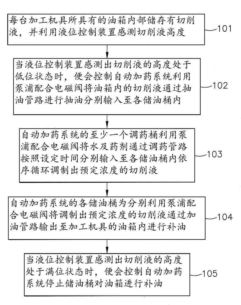
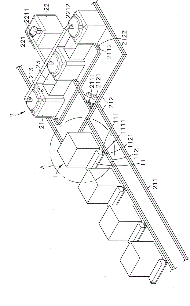
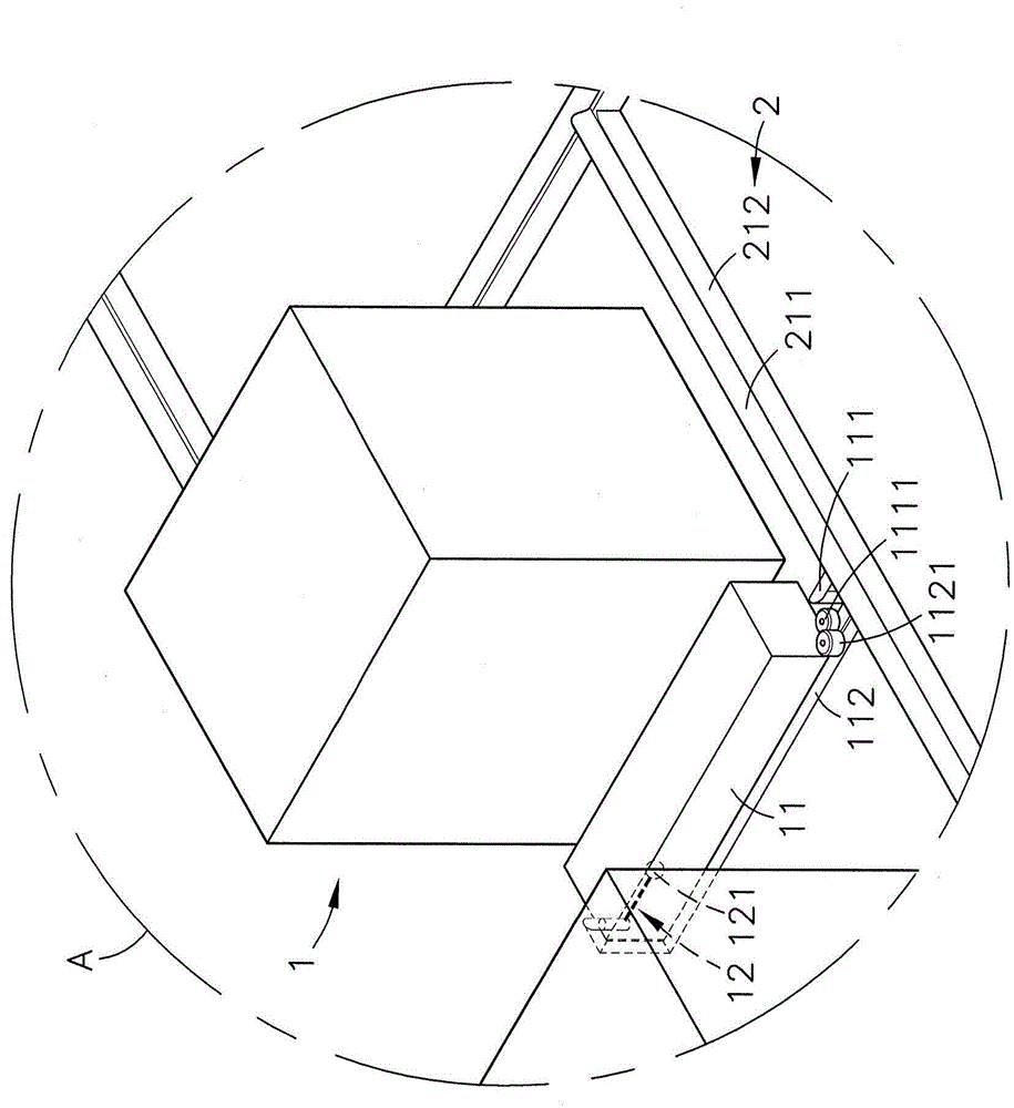
[0032] see figure 1 , figure 2 , image 3 As shown, it is a flow chart of the steps of the present invention, a three-dimensional appearance diagram of a preferred embodiment, and image 3 It can be clearly seen from the figure that the present invention includes a processing machine 1 and an automatic dosing system 2, so the main components and features of this case are described in detail as follows, wherein:

[0033] The processing tool 1 can be a lathe, a milling machine, a planer, a drilling machine, a numerically controlled machine tool (NC), a computer numerically controlled machine tool (CNC) or other various processing master machines, and the processing to...


PUM


Abstract

The invention provides a processing method for an automatic dosing system. The processing method for the automatic dosing system includes the steps that a liquid level control device in an oil tank of each machining machine is used for sensing the height of cutting fluid, when the height of the cutting fluid is in a low level state, the automatic dosing system is controlled to use pumps in cooperation with electromagnetic valves to transport the cutting fluid in the oil tanks into oil storage barrels respectively through oil pumping pipelines, and a medicine preparing barrel uses the pumps in cooperation with the electromagnetic valves to transport water and agentia into the oil storage barrels respectively through a medicine preparing pipeline according to the set time, the cutting fluid with preset concentration can be prepared in sequence in a circulating mode, and the oil storage barrels use the pumps in cooperation with the electromagnetic valves to transport the prepared cutting fluid with the preset concentration into the oil tanks to refuel through a refueling pipeline. The automatic dosing system can automatically refuel the oil tank of each machining machine, working hours and cost of manpower detection and refueling can be effectively saved, and the concentration of the cutting fluid in the oil tanks can be maintained, so that the machining precision of workpieces can be improved, and the service life of cutting tools can be prolonged.

Description

technical field [0001] The invention provides a treatment method of an automatic dosing system, especially the automatic dosing system can be used to automatically replenish the fuel tank of each processing tool, so as to effectively save the man-hours and costs spent on manual inspection and refueling, and It can maintain the concentration of cutting fluid in the oil tank, so as to improve the precision of workpiece processing and prolong the service life of cutting tools. Background technique [0002] Today's manufacturing industry is facing labor shortages, rising awareness of environmental protection, rising labor and operating costs, and pressure from labor-intensive to technology-intensive transformation. Most manufacturers respond to rising costs by relocating industries or introducing foreign labor. Or use production line automation technology and fixture assistance to improve the operating system and reduce costs, so as to achieve the purpose of reducing manpower, s...

Claims


Application Information

Patent Timeline
IPC IPC(8): B23Q11/10
CPCB23Q11/1038
Inventor 沈伟勋
Owner DESIGNING FUTURE TECH
Why Eureka
Try Eureka