Constant-tension adhesive tape rewinder allowing tape roll discharging position to be controlled

A rewinding machine and constant tension technology, which is applied in the directions of winding strips, thin material processing, transportation and packaging, etc., can solve the problems of rewinding processing requirements of polytetrafluoroethylene tapes, deformation of cylindrical tapes, and low production efficiency and other problems, to achieve the effect of small stress, smooth tape and high utilization rate

Inactive Publication Date: 2015-05-20
SICHUAN UNIV
View PDF9 Cites 19 Cited by
  • Summary
  • Abstract
  • Description
  • Claims
  • Application Information

AI Technical Summary

Problems solved by technology

[0004] The constant tension adhesive tape rewinder with controllable unwinding position provided by the present invention is to solve the serious deformation, deviation, poor quality, low pass rate and lo

Method used


Image

  • Constant-tension adhesive tape rewinder allowing tape roll discharging position to be controlled
  • Constant-tension adhesive tape rewinder allowing tape roll discharging position to be controlled
  • Constant-tension adhesive tape rewinder allowing tape roll discharging position to be controlled

Examples


Embodiment Construction

[0018] The constant tension adhesive tape rewinder with controllable unwinding position of this embodiment is formed as follows:

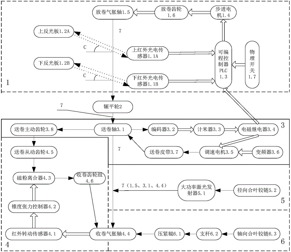
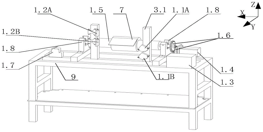
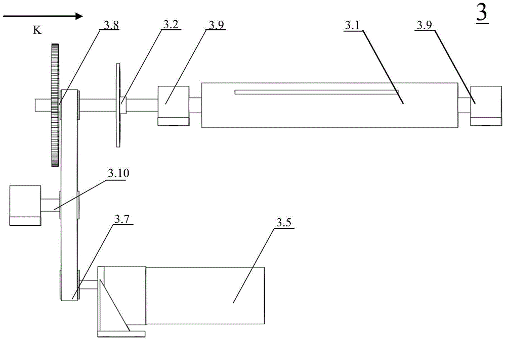
[0019] See Image 6 , on the frame 9, at the unwinding end, there is an unwinding air shaft 1.5 supported on the unwinding simply supported beam with tape 7 rolled on it. At the rewinding end, a rewinding inflatable shaft 4.4 supported on a rewinding simply supported beam is provided with an adhesive tape 7 . See figure 1 , between the unwinding air shaft 1.5 and the winding air shaft 4.4 are provided with: double closed-loop unwinding position control system 1; flattening wheel 2; sending reel 3.1 and winding length control system 3; semi-closed loop at the rewinding end Tension control system 4, deviation correcting device 5, pressing assembly 6. In order to ensure the strength of the frame, 4040 European standard heavy-duty industrial aluminum profiles and special connectors and adjustment parts can be used in actual production.

[0020] 1) ...


PUM


Abstract

The invention discloses a constant-tension adhesive tape rewinder allowing the tape roll discharging position to be controlled. An unwinding inflatable shaft around which adhesive tape is wound and a winding inflatable shaft are arranged on a machine frame, and a roll conveying shaft is arranged between the unwinding inflatable shaft and the winding inflatable shaft. A dual-closed-loop roll discharging position control system comprising an upper infrared photoelectric sensor, a lower infrared photoelectric sensor, a PLC, a stepping motor, and the like is arranged at the roll discharging position. The adhesive tape enters a flattening wheel. A winding length control system comprising an encoder, a meter counter, an electromagnetic relay, an adjustable-speed motor and a frequency converter is arranged at the position of a roll conveying shaft. A semi-closed-loop tension control system comprising an infrared rotary sensor, a taper tension controller, a magnetic powder clutch and the like is arranged at the roll receiving end, and a manual deviation rectifying device used for laser calibration and positioning and a pressing assembly are also arranged. By the adoption of the constant-tension adhesive tape rewinder allowing the tape roll discharging position to be controlled, excessive stress and serious deformation, caused by major tension fluctuation, of the adhesive tap are completely avoided, the initial precision and the operating precision of the adhesive tape are high, and the quality of adhesive tape products is greatly improved. Meanwhile, the length of an adhesive tape roll can be controlled, winding efficiency, unwinding efficiency, replacing efficiency and installation efficiency are high, and using and operation are convenient and fast. The adhesive tape rewinder can be used for producing a big polytetrafluoroethylene adhesive tape roll in the required size.

Description

(1) Technical field [0001] The invention relates to a rewinding device for a cylindrical tape product, which is to make the glue-coated cylindrical tape roll into a required size or required size tape roll through the rewinding device. Especially rewinders for PTFE film tubular tape products. It belongs to the conveying category of thin materials (B65H). (2) Technical background [0002] At present, the rewinding machine has been widely used, and the relevant requirements for the rewinding machine are also different for different materials and different processes of film tubular tapes. The production of existing polytetrafluoroethylene film cylindrical adhesive tape, at first is to cover the polytetrafluoroethylene raw material film with the silicone pressure film after its surface treatment through the film processing equipment by what can be called a glue-coating roll mold machine or a rewinding machine. Sensitive adhesives to obtain Teflon film tubular tapes. Then, thr...

Claims


Application Information

Patent Timeline
IPC IPC(8): B65H23/185B65H23/198B65H16/06B65H18/06B65H26/06
CPCB65H16/06B65H18/06B65H23/185B65H23/198B65H26/06B65H2511/11
Inventor 赵武王晨王志勇陈华为王超宇郭鑫罗纯静罗涛高琪刘巧王瑞施天天高立强张凯
Owner SICHUAN UNIV
Why Eureka
Try Eureka