Eureka AIR delivers breakthrough ideas for toughest innovation challenges, trusted by R&D personnel around the world.

Digital control oscillator and magnetic resonance imaging system

A digitally controlled oscillation and frequency control word technology, applied in the fields of automatic power control, sensors, medical science, etc., can solve the problem of reducing the spurious-free dynamic range of the output signal, so as to improve the spurious-free dynamic range, signal-to-noise The effect of increasing and reducing costs

Active Publication Date: 2015-05-20
SHANGHAI UNITED IMAGING HEALTHCARE
View PDF5 Cites 3 Cited by
  • Summary
  • Abstract
  • Description
  • Claims
  • Application Information

AI Technical Summary

Problems solved by technology

[0007] However, in digitally controlled oscillators, the phase intercept error is the main source of frequency spurs of the periodic signal output by the digitally controlled oscillator, and the frequency spurs reduce the spurious-free dynamic range (SFDR, Spurious Free Dynamic range)

Method used


Image

  • Digital control oscillator and magnetic resonance imaging system
  • Digital control oscillator and magnetic resonance imaging system
  • Digital control oscillator and magnetic resonance imaging system

Examples


Embodiment 1

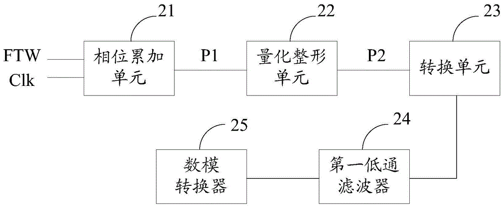
[0053] figure 2 is a schematic structural diagram of the digitally controlled oscillator according to Embodiment 1 of the present invention. refer to figure 2 , the digitally controlled oscillator includes a phase accumulation unit 21 , a quantization shaping unit 22 and a conversion unit 23 .

[0054] The phase accumulation unit 21 is adapted to perform accumulation processing on the frequency control word FTW under the control of the clock signal Clk to generate the first phase signal P1. The clock signal Clk can be generated by a reference clock, and the frequency control word FTW, also called a phase increment, can be generated by a frequency control word generator, and its number of bits determines the frequency resolution of the periodic signal output by the digitally controlled oscillator. Therefore, the digitally controlled oscillator in this embodiment may further include a reference clock for generating the clock signal Clk and a frequency control word generator ...

Embodiment 2

[0084] Figure 8 It is a schematic structural diagram of a digitally controlled oscillator according to Embodiment 2 of the present invention. refer to figure 2 , the digitally controlled oscillator includes a phase accumulation unit 81, a quantization shaping unit 82, a conversion unit 83, a first low-pass filter 84, a digital-to-analog converter 85, and a second low-pass filter 86, wherein the phase accumulation The unit 81 , the quantization and shaping unit 82 , the conversion unit 83 , the first low-pass filter 84 and the digital-to-analog converter 85 are similar to those in Embodiment 1, and will not be repeated here.

[0085] The second low-pass filter 86 is suitable for low-pass filtering the periodic signal generated by the digital-to-analog converter 85. Compared with Embodiment 1, the signal of the periodic signal output by the digital-to-analog converter in this embodiment is The noise ratio is higher.

[0086] The technical solution of the present invention a...


PUM


Abstract

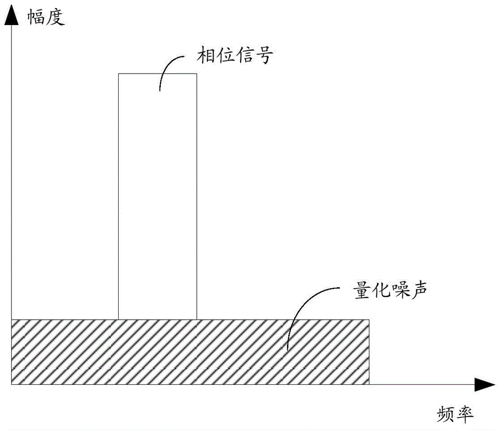
Disclosed are a digital control oscillator and a magnetic resonance imaging system. The digital control oscillator comprises a phase accumulation unit, a quantitative shaping unit and a conversion unit. The phase accumulation unit is used for accumulating frequency control words to generate first phase signals; the quantitative shaping unit is used for quantizing the first phase signals to generate second phase signals, performing low-frequency attenuation and high-frequency amplification on quantizing noises generated from quantization and performing low-pass filtering on the quantizing noises subjected to low-frequency attenuation and high-frequency amplification; the conversion unit is used for outputting waveform data corresponding to the second phase signals. Since the quantizing noises are shaped by the digital control oscillator, the signal to noise ratio and the stray-free dynamic range of outputted periodic signals are increased.

Description

technical field [0001] The invention relates to the technical field of magnetic resonance imaging, in particular to a digitally controlled oscillator and a magnetic resonance imaging system. Background technique [0002] Magnetic Resonance Imaging (MRI, Magnetic Resonance Imaging) is an important field of nuclear magnetic resonance applications. Due to its excellent resolution of human soft tissues, imaging parameters can provide rich diagnostic information, and no ionizing radiation damage to the human body. Resonance imaging system has become one of the main tools of medical clinical diagnosis. [0003] In magnetic resonance imaging systems, radio frequency signals are usually transmitted with some type of carrier modulation, and the bandwidth of the transmitted signal is limited to a frequency band centered on the carrier signal, such as double-sideband modulation, or in a frequency band adjacent to the carrier signal on, such as single sideband modulation. Regardless o...

Claims


Application Information

Patent Timeline
Patent Type & Authority Applications(China)
IPC IPC(8): H03L7/099A61B5/055
Inventor 谢强封勇福
Owner SHANGHAI UNITED IMAGING HEALTHCARE
Why Eureka
Eureka Blog
Learn More