
Optically controlled phased array radar system based on wavelength routing

A radar system and wavelength technology, which is applied in the field of radar systems, can solve problems such as very high accuracy requirements for optical fiber length, affect delay performance, and complex structure, and achieve the effects of small loss, improved stability, and small size

Active Publication Date: 2015-05-27
ZHEJIANG UNIV
View PDF5 Cites 14 Cited by
  • Summary
  • Abstract
  • Description
  • Claims
  • Application Information

AI Technical Summary

Problems solved by technology

In the optical fiber-based real delay device, each microwave array element has a corresponding delay line array. As the number of channels increases, the number of delay line arrays will increase linearly, and the number of optical fibers will increase exponentially. , causing disadvantages such as increased loss, complex structure, bulky volume, and huge cost; and, most of the above methods need to use a large number of optical switches to realize the selection of delay lines. As the number of channels increases, the number of optical switches will increase exponentially. It will cause disadvantages such as increased loss; at the same time, because most of the above methods use the difference in fiber length to introduce delay, this requires very high accuracy of fiber length; in addition, the problem of fiber grating overlap and chirped fiber grating jitter will affect Delayed performance

Method used


Image

  • Optically controlled phased array radar system based on wavelength routing
  • Optically controlled phased array radar system based on wavelength routing
  • Optically controlled phased array radar system based on wavelength routing

Examples


Embodiment Construction

[0037] The present invention will be described in further detail below in conjunction with the accompanying drawings and specific embodiments.

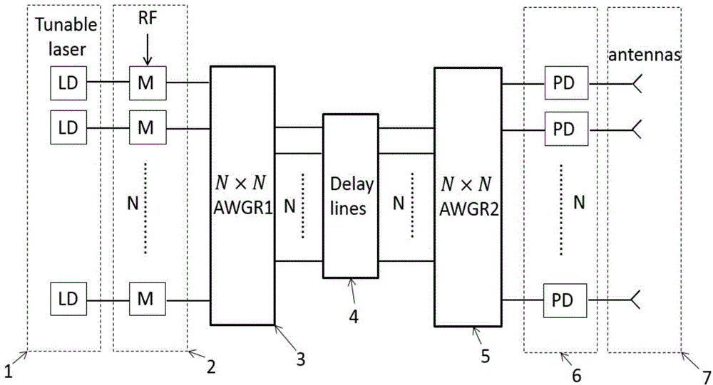
[0038] Such as figure 1 As shown, the present invention includes a tunable semiconductor laser 1, a modulator 2, a first arrayed waveguide grating router 3, a delay line array 4, a second arrayed waveguide grating router 5 and a semiconductor detector 6 connected in sequence, and the semiconductor detector 6 is connected There is an antenna 7; the first arrayed waveguide grating router 3, the delay line array 4, and the second arrayed waveguide grating router 5 constitute an optical true time delay (OTTD) device.

[0039] N tunable semiconductor lasers (TLS) 1 send out multiple optical signals of different wavelengths and use microwave signals (RF) to load and modulate them into optical carriers through their respective modulators 2, and the optical carriers are transmitted to the first arrayed waveguide grating router (AWGR) 3 N out...


PUM


Abstract

The invention discloses an optically controlled phased array radar system based on wavelength routing. N tunable semiconductor lasers emit multiple paths of optical wave signals different in wavelength; microwave signals are loaded and modulated through respective modulators, transmitted to a first array waveguide grating router, transmitted to a second array waveguide grating router through a delayed linear array and transmitted to N semiconductor detectors for demodulation; the semiconductor detectors emit the demodulated microwave signals through an antenna. The tunable semiconductor lasers are used to change the wavelengths for switching the delayed linear array, so that the use of a large amount of optical switches is avoided; with an integrated optics method, an overlapping problem of fiber Bragg gratings is solved, the two array waveguide grating routers and the delayed linear array are integrated on the same substrate, and the precision of the delay line length is guaranteed, so that the stability of the system is improved, the cost is reduced, and the system has the advantages of small size, low loss, light mass, high precision, electromagnetic interference resistance and the like.

Description

technical field [0001] The invention relates to a radar system, in particular to an optically controlled phased array radar system based on wavelength routing, which relates to phased array radar technology. Background technique [0002] Compared with traditional radars, optically controlled phased array radar has many advantages such as small size, light weight, low loss, anti-electromagnetic interference, wide instantaneous bandwidth, and no beam tilt. Therefore, the optical true time-delay module, which is the core technology of optically controlled phased array radar, has become a research hotspot in this field. [0003] In the prior art both at home and abroad, many designs of optical real-time delay modules are also provided. There are methods to achieve time delay based on the change of the length of ordinary optical fibers; there are also methods to achieve time delay by reflecting light waves of different wavelengths at different positions of fiber Bragg gratings; ...

Claims


Application Information

Patent Timeline
IPC IPC(8): G01S17/02G01S7/48
CPCG01S17/02
Inventor 何建军陈阳郎婷婷
Owner ZHEJIANG UNIV
Learn More