Image enhancer

A technology of image intensifier and outer casing, which is applied in the field of imaging, can solve the problems of unstable optical path, bulky, difficult installation, etc., and achieve the effect of simple structure, reduced overall weight, and convenient installation

Inactive Publication Date: 2015-05-27
SHAANXI ZIZHU ELECTRON
View PDF0 Cites 1 Cited by
  • Summary
  • Abstract
  • Description
  • Claims
  • Application Information

AI Technical Summary

Problems solved by technology

[0005] The image intensifier in the X-ray detection system is an essential component. After the X-ray passes through the PCB board, the image intensifier is used to receive and intensify the image, and finally the image information on the image intensifier is extracted by the CCD camera and handed over to the computer for processing; The traditional image intensifier has the disadvantages of being bulky, difficult to install, and unstable in the optical path

Method used


Image

  • Image enhancer

Examples


Embodiment Construction

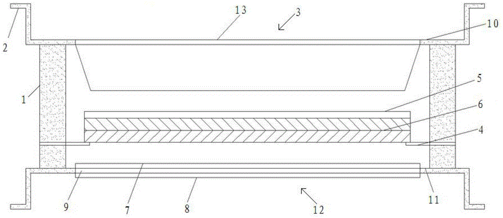
[0023] Such as figure 1 As shown, the present invention includes an outer casing 1 of cylindrical structure, the upper end of the outer casing 1 is provided with a top cover 10, and the bottom end of the outer casing 1 is provided with a bottom cover 11, and the top cover 10 and the bottom cover 11 are all sealed. Installed on the outer casing 1, the top cover 10 is provided with an input window 3, the fiber optic panel 13 is sealed and installed on the input window 3, the fiber optic panel 13 is covered with a high-transmittance film, and the bottom cover 11 There is an output window 12 corresponding to the input window 3, and the optical fiber panel 2 9 is sealed and installed on the output window 12. The side of the optical fiber panel 9 close to the inner cavity of the outer casing 1 is coated with a phosphor layer 7, and the optical fiber The other side of the panel two 9 is covered with a lead glass layer 8, and a microchannel plate 6 is arranged at a position above the ...


PUM


Abstract

The invention discloses an image enhancer which comprises an outer housing in a cylinder structure, wherein a top cap is arranged at the upper end of the outer housing; a bottom cap is arranged at the bottom end of the outer housing; the top cap and the bottom cap are mounted on the outer housing in a sealing manner; an input window is formed in the top cap; an optical fiber panel I is mounted on the input window in a sealing manner; an output window is formed in the bottom cap; an optical fiber panel II is mounted on the output window in a sealing manner; one side, close to an inner cavity of the outer housing, of the optical fiber panel II is coated with a fluorescent powder layer; the other side of the optical fiber panel II is covered with a lead glass layer; a microchannel plate is arranged in a position, above the output window, in the inner cavity of the outer housing; a photoelectric cathode is arranged on the microchannel plate; a plurality of supporting plates are arranged on an inner wall of the outer housing; and the microchannel plate is bonded on the supporting plates in a sealing manner. The enhancer is simple in structure, reasonable in design, convenient to mount, good in overall structure sealability, good in light path stability, stable and reliable in working performance, strong in practicability, good in use effect and high in popularization value and effectively avoids X-ray leakage.

Description

technical field [0001] The invention belongs to the field of image technology, and in particular relates to an image intensifier. Background technique [0002] With the rapid development of electronic science and technology, the miniaturization of packaging, the high density of assembly, and the continuous emergence of various new packaging technologies, strict requirements have been put forward for the quality inspection of surface mount technology (SMT) assembly products. Traditional manual visual inspection, automatic optical inspection (AOI), laser inspection, in-circuit testing (ICT) and other inspection technologies can no longer meet the requirements. [0003] The use of automatic X-ray inspection technology (AXI) has become the main method to solve the problem. It can not only detect hidden solder joints, such as BGA (Ball Grid Array Package), but also perform qualitative and quantitative analysis on the detection results, find electronic assembly failures in time, ...

Claims


Application Information

Patent Timeline
Patent Type & Authority Applications(China)
IPC IPC(8): H01J31/50H01J29/86
CPCH01J31/505H01J29/861H01J31/507
Inventor 田伟国
Owner SHAANXI ZIZHU ELECTRON
Why Eureka
Try Eureka