Multi-input and multi-output optical communication system and signal recovery method thereof

An optical communication system and optical signal technology, applied in the field of optical communication, can solve problems such as complex two-dimensional code coding rules, single light source color, and inability to use white light source, so as to realize large-capacity signal transmission, improve communication capacity, and system The effect of simple structure

Active Publication Date: 2015-05-27
NANJING UNIV OF POSTS & TELECOMM
View PDF5 Cites 9 Cited by
  • Summary
  • Abstract
  • Description
  • Claims
  • Application Information

AI Technical Summary

Problems solved by technology

For example, different channels in traditional MIMO visible light communication technology use different single-frequency signal light sources, but such light sources have a single color and cannot use the white light source used in traditional lighting.
For another example, some visible light MIMO technologies use two-dimensional code technology for signal encoding, but the coding rules of two-dimensional code are complicated, so there are special requirements for light source arrangement
Moreover, the signal emission light source can only use a point light source, but cannot use a surface light source, which reduces the comfort of the human eye.

Method used


Image

  • Multi-input and multi-output optical communication system and signal recovery method thereof
  • Multi-input and multi-output optical communication system and signal recovery method thereof
  • Multi-input and multi-output optical communication system and signal recovery method thereof

Examples


specific Embodiment

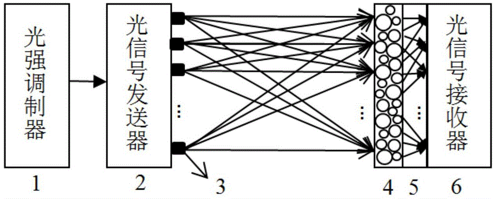
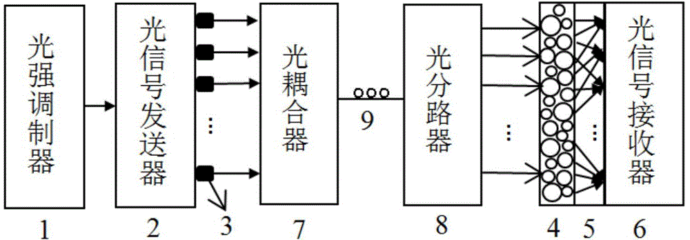
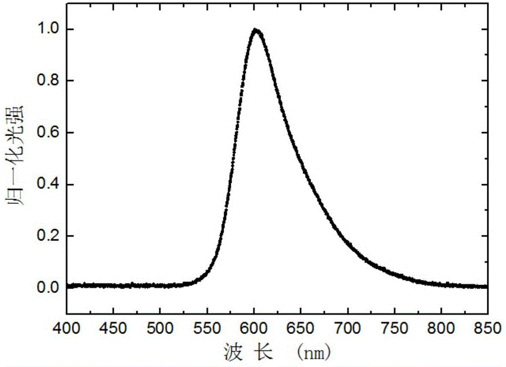
[0069] The optical signal transmitter in this example is composed of 8 identical white light LEDs, and each LED is attached with a different filter film, which are respectively recorded as: filter film a, filter film b, filter film c, filter film d, filter film e , filter film f, filter film g and filter film h, these 8 filter films are different from each other, the difference is that they have different transmittances to light of different wavelengths. The spectrum of the light emitted by the LED after passing through the eight filter films is as follows: Figure 3 to Figure 10 As shown, each LED will send signals in different wavelength ranges after passing through different filter films, which is equivalent to using multiple light sources with spectral differences, and distinguishing them by the intensity of the emitted light ("higher light intensity" means The signal "1", "the light intensity is dim or no light" represents the signal "0"; of course, the reverse is also po...


PUM


Abstract

The invention discloses a multi-input and multi-output optical communication system and a signal recovery method thereof. The multi-input and multi-output optical communication system comprises an optical signal transmitting end and an optical signal receiving end, wherein the optical signal transmitting end comprises a light intensity modulation unit and an optical signal sending unit which are mutually connected, the optical signal sending unit comprises n broadband light sources which have mutually overlapped, but not totally identical frequency spectra, and the light intensity modulation unit is used for respectively modulating n lines of signals to corresponding optical modulation signals generated by the n broadband light sources; the optical signal receiving end comprises a light splitter, an optical signal receiver and a signal processing unit; the light splitter enables incident light at different frequencies to form different light intensity distributions after the incident light passes the light splitter, and the light intensity angle distributions generated by the incident light at the same frequency after the incident light passes the different parts of the light splitter are also different; the optical signal receiver is an optical detector array constituted by n optical detectors with same frequency spectral response. The multi-input and multi-output optical communication system disclosed by the invention can realize large-capacity signal transmission while illuminating and is further simple in structure and easy to implement.

Description

technical field [0001] The present invention relates to the technical field of optical communication, in particular to a multiple-input multiple-output (Multiple-Input Multiple-Output, MIMO) optical communication system and a signal recovery method thereof. Background technique [0002] Optical communication is a communication method using light waves as the carrier. In wireless communication, visible light communication (Visible Light Communications, VLC) technology develops rapidly and becomes a new wireless communication method. By adding data transmission auxiliary functions to public basic lighting facilities and combining communication with indoor lighting sources, an indoor visible light wireless communication network can be constructed to realize wireless transmission of information from the server to the client. Since visible light is closely related to daily life, many devices in offices, homes and public places contain visible light sources, such as office lights...

Claims


Application Information

Patent Timeline
Patent Type & Authority Applications(China)
IPC IPC(8): H04B10/50H04B10/60H04B10/116
Inventor 杨涛许超何浩培黄维李兴鳌韦玮仪明东
Owner NANJING UNIV OF POSTS & TELECOMM
Why Eureka
Try Eureka