Radial forging type strain-induced semi-solid die forging process for outer cylinder forged piece of aircraft landing gear

A technology for aircraft landing gear and semi-solid die forging, which is used in metal processing equipment and other directions, can solve the problems of low fatigue strength and stability, high mold heating temperature, and large forging forming force, etc. Low pressure and uniform distribution

Inactive Publication Date: 2015-06-03
XI AN JIAOTONG UNIV
View PDF4 Cites 13 Cited by
  • Summary
  • Abstract
  • Description
  • Claims
  • Application Information

AI Technical Summary

Problems solved by technology

[0004] At present, the main structural parts of aircraft landing gear are mainly made of ultra-high-strength steel and titanium alloy. For example, foreign civil aircraft landing gear mainly uses high-performance materials such as 300M steel, 4340 steel, 30CrMnSiNi2A, high-strength titanium alloy and aluminum alloy. , its manufacturing process mainly includes: integral forging billet, physical and chemical testing of forgings and ultrasonic flaw detection, large margin CNC "skinning" processing of forging blank surface, material removal processing of inner hole cavity, etc., among which, compared with traditional aircraft landing gear Most of the machining methods used have the disadvantages of relatively low fatigue strength and stability. The overall forging forming process can improve the uniformity of the structure of the aircraft landing gear, good streamlines, and improve its performance. However, in the process of forging blanks, There are disadvantages of high mold heating temperature, easy damage, large forging force required, and high energy consumption

Method used


Image

  • Radial forging type strain-induced semi-solid die forging process for outer cylinder forged piece of aircraft landing gear
  • Radial forging type strain-induced semi-solid die forging process for outer cylinder forged piece of aircraft landing gear
  • Radial forging type strain-induced semi-solid die forging process for outer cylinder forged piece of aircraft landing gear

Examples


Embodiment Construction

[0021] The present invention will be described in detail below in conjunction with the accompanying drawings.

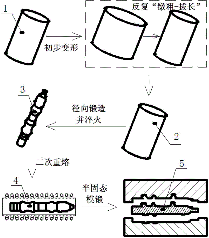
[0022] refer to figure 1 , the radial forging type strain-induced semi-solid die forging process of aircraft landing gear outer cylinder forgings, comprising the following steps:

[0023] 1) Preliminary deformation of the bar: first prepare the metal bar 1 made of ultra-high-strength steel or titanium alloy for forming the forging of the outer cylinder of the aircraft landing gear; then preheat the metal bar 1 and perform repeated upsetting and elongation , to obtain a distorted metal rod 2 that stores distortion energy;

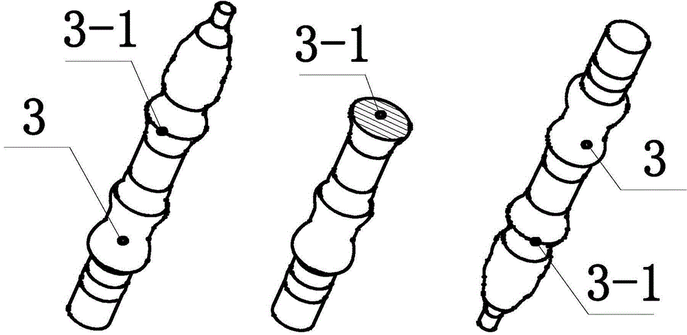
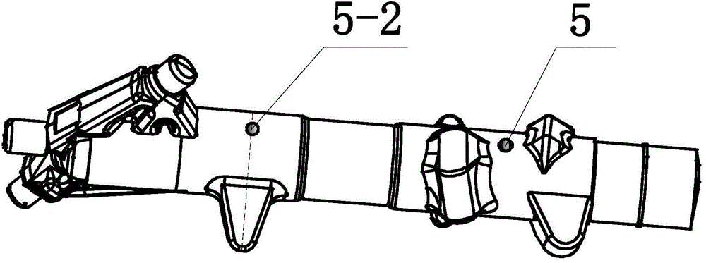
[0024] 2) Bar radial forging: refer to figure 2 , image 3 , Figure 4 and Figure 5 , using residual heat to radially forge the distorted metal bar 2 obtained in step 1) to obtain a radially forged distorted billet 3, specifically: using a radial forging machine to symmetrically distribute four hammerheads 6 around the billet, High-frequenc...


PUM


Abstract

The invention relates to a radial forging type strain-induced semi-solid die forging process for an outer cylinder forged piece of an aircraft landing gear. The process includes the following steps of: preheating a metal bar which is made of super strength steel or titanium alloy and is used for forming the outer cylinder forged piece of the aircraft landing gear, and repeatedly upsetting and lengthening the metal bar to obtain a distorted metal bar with storage of distortion energy; forging the distorted metal bar in a radial direction through the afterheat to obtain a radially-forged distorted blank, and quenching the radially-forged distorted blank; re-melting the radially-forged distorted blank to obtain a semi-solid blank of the outer cylinder forged piece of the aircraft landing gear of which solid fraction is between 40% and 60%; finally performing semi-solid die forging on the semi-solid blank of the outer cylinder forged piece of the aircraft landing gear to obtain a formed outer cylinder forged piece of the aircraft landing gear. The process has characteristics of simplicity in process, low forming pressure, high material utilization rate and good mechanical properties of products.

Description

technical field [0001] The invention belongs to the technical field of manufacturing aircraft landing gear outer cylinder forgings, in particular to a radial forging strain-induced semi-solid die forging process for aircraft landing gear outer cylinder forgings. Background technique [0002] In the 1970s, Professor Flemings of the Massachusetts Institute of Technology proposed the concept of semi-solid forming of metal parts. The so-called semi-solid forging (Semi-solid forging-SSF), also known as thixoforging, is to heat the semi-solid billet to a semi-solid state with about 50% volume of liquid phase and then heat it in a semi-solid state with a slightly higher preheating temperature. A forging process is performed in the mold cavity to obtain the required close-to-size finished parts. This is a new process between liquid forming (casting) and strand forming (press processing). [0003] Aircraft landing gear is one of the main functional parts of the aircraft, which is us...

Claims


Application Information

Patent Timeline
IPC IPC(8): B21J5/02B21J1/06
Inventor 赵升吨王永飞张晨阳范淑琴
Owner XI AN JIAOTONG UNIV
Why Eureka
Try Eureka