Urban rail vehicle traction system

A vehicle traction and urban rail technology, applied in the field of rail vehicle power, can solve the problem that the vehicle cannot run for a long distance, and achieve the effect of improving performance

Active Publication Date: 2015-06-03
CRRC DALIAN R & D CO LTD
View PDF5 Cites 20 Cited by
  • Summary
  • Abstract
  • Description
  • Claims
  • Application Information

AI Technical Summary

Problems solved by technology

[0005] The invention provides an urban rail vehicle traction system, which is used to solve the technical problem in

Method used


Image

  • Urban rail vehicle traction system
  • Urban rail vehicle traction system

Examples


Embodiment Construction

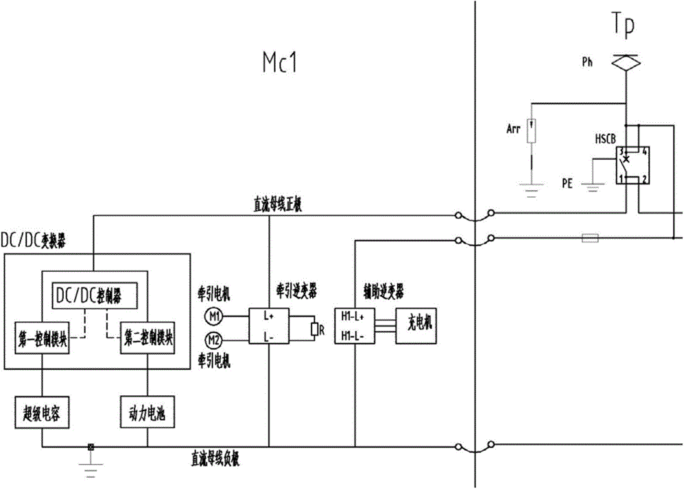
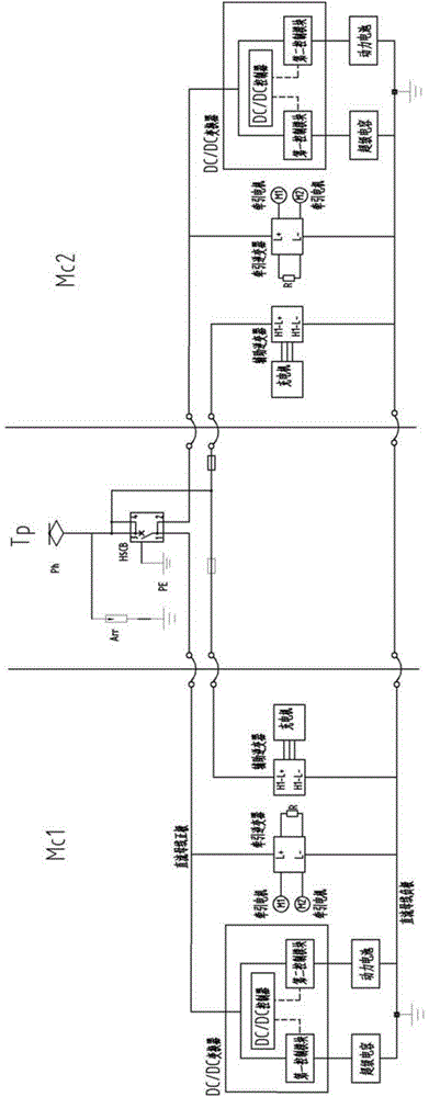
[0021] figure 1 It is a schematic structural diagram of an urban rail vehicle traction system according to an embodiment of the present invention, as figure 1 As shown, MC1 is a motor car with a driver's cab; TP is a trailer with a pantograph; the urban rail vehicle traction system of this embodiment is generally arranged on a motor car, and the traction system includes a power device and an energy storage device; the power device includes a traction Inverter and traction motor. The input terminals of the traction inverter are respectively connected to the positive pole and negative pole of the DC bus of the power supply network. The traction inverter is used for mutual conversion of DC and AC power. The output terminal of the traction inverter is connected to the traction motor. The traction motor is used to power the vehicle and convert kinetic energy into alternating current when the vehicle brakes. The energy storage device includes: a DC / DC converter, a supercapacitor an...


PUM


Abstract

The invention provides an urban rail vehicle traction system. The system comprises a power device and an energy storing device; the power device comprises a traction inverter connected with a power supply network, and a traction motor connected with the output end of the traction inverter; the energy storing device comprises a DC/ DC convertor, a super capacitor and a power battery; the super capacitor and the power battery are connected in parallel; a negative electrode of the super capacitor is connected with the negative electrode of a DC bus of the power supply network, and while a positive electrode of the super capacitor is connected with the positive electrode of the DC bus of the power supply network through the DC/ DC convertor; the DC/ DC convertor controls the super capacitor and the power battery to charge and discharge, and the discharged electricity is supplied to the power device through the DC/ DC convertor. According to the traction, the super capacitor and the power battery are connected in parallel to be used as an energy supply source, and therefore, the performances of the urban rail vehicle crossing a non-power area can be fully improved when separating from the power supply network.

Description

technical field [0001] The invention relates to traction power technology, in particular to an urban rail vehicle traction system, which belongs to the technical field of rail vehicle power. Background technique [0002] With the increasingly tight road resources, the catenary erection space of urban rail vehicles is increasingly restricted by various buildings or roads. It is not easy to build a catenary in the depot, so a light rail vehicle that can pass through the non-electric zone through energy storage is needed. [0003] In the prior art, catenary and on-board supercapacitors are usually used as the vehicle power supply system. In this form of power supply system, when the catenary has power, the catenary serves as the initial voltage source to supply power to the traction motor to drive the traction motor; The voltage source supplies power to the traction motor to drive the traction motor. [0004] However, due to the low energy stored in supercapacitors, the ener...

Claims


Application Information

Patent Timeline
IPC IPC(8): B60L9/00B60L11/18
CPCY02T10/70Y02T10/72
Inventor 任宝兵梁佳昱赵立超
Owner CRRC DALIAN R & D CO LTD
Why Eureka
Try Eureka