Vacuum pulsation ultrasonic drying equipment

A drying equipment, vacuum ultrasonic technology, applied in the direction of drying solid materials, local agitation dryer, lighting and heating equipment, etc., can solve the problems of low production efficiency, reduced activity, high production cost, etc.

Active Publication Date: 2015-06-03
INST OF PROCESS ENG CHINESE ACAD OF SCI
View PDF6 Cites 15 Cited by
  • Summary
  • Abstract
  • Description
  • Claims
  • Application Information

AI Technical Summary

Problems solved by technology

In current production, vacuum drying, spray drying, and freeze drying are generally used for drying. Among them, spray drying and freeze drying have problems such as expensive equipment and high production costs. However, the existing vacuum drying requires long drying time, high energy consumption, and low production efficiency. shortcoming
[0003] For heat-sensitive plant natural products, heating and drying will cause the structure of these active ingredients to bre

Method used


Image

  • Vacuum pulsation ultrasonic drying equipment
  • Vacuum pulsation ultrasonic drying equipment
  • Vacuum pulsation ultrasonic drying equipment

Examples


Embodiment 1

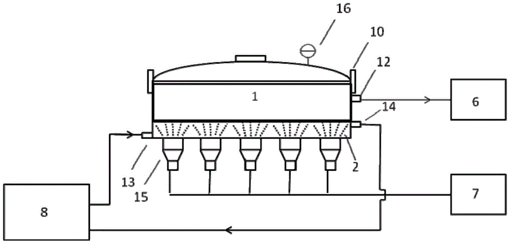
[0094] A vacuum ultrasonic drying equipment, such as figure 1 As shown, it includes the following structures: drying chamber 1, cooling jacket layer 2, vacuum control system 6, ultrasonic control system 7, circulation refrigeration control system 8, quick opening valve 10, air suction port 12, circulation refrigeration liquid inlet 13, circulation refrigeration Liquid outlet 14, several ultrasonic transducers 15, vacuum gauge 16; The ultrasonic transducer 15 is at the bottom of the cooling jacket layer 2, and the ultrasonic energy is transmitted to the drying chamber 1 through the cooling jacket layer 2; several ultrasonic transducers The transducers 15 are all controlled by the ultrasonic control system 7; the vacuum control system 6 extracts the gas in the drying chamber 1 through the suction port 12 located on the side of the drying chamber; the circulating refrigerant in the cooling jacket layer 2 is provided by the circulating freezing control system 8 The circulating ref...

Embodiment 2

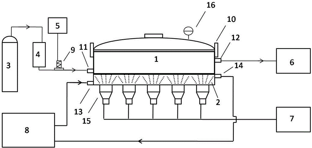
[0096] A vacuum pulsation ultrasonic drying equipment, such as figure 2As shown, it includes the following structures: drying chamber 1, cooling jacket layer 2, air supply system 3, dry filter 4, switch control system 5, vacuum control system 6, ultrasonic control system 7, cycle refrigeration control system 8, valve 9 , quick opening valve 10, air inlet 11, air extraction port 12, circulating refrigerant inlet 13, circulating refrigerant outlet 14, several ultrasonic transducers 15, vacuum gauge 16; the several ultrasonic transducers 15 are uniform Distributed at the bottom of the cooling jacket layer 2, the ultrasonic energy is transmitted to the drying chamber 1 through the cooling jacket layer 2; the several ultrasonic transducers 15 are controlled by the ultrasonic control system 7; the vacuum control system 6 is located on the side of the drying chamber The gas extraction port 12 of the air extraction port 1 extracts the gas in the drying chamber 1; the circulating refr...

Embodiment 3

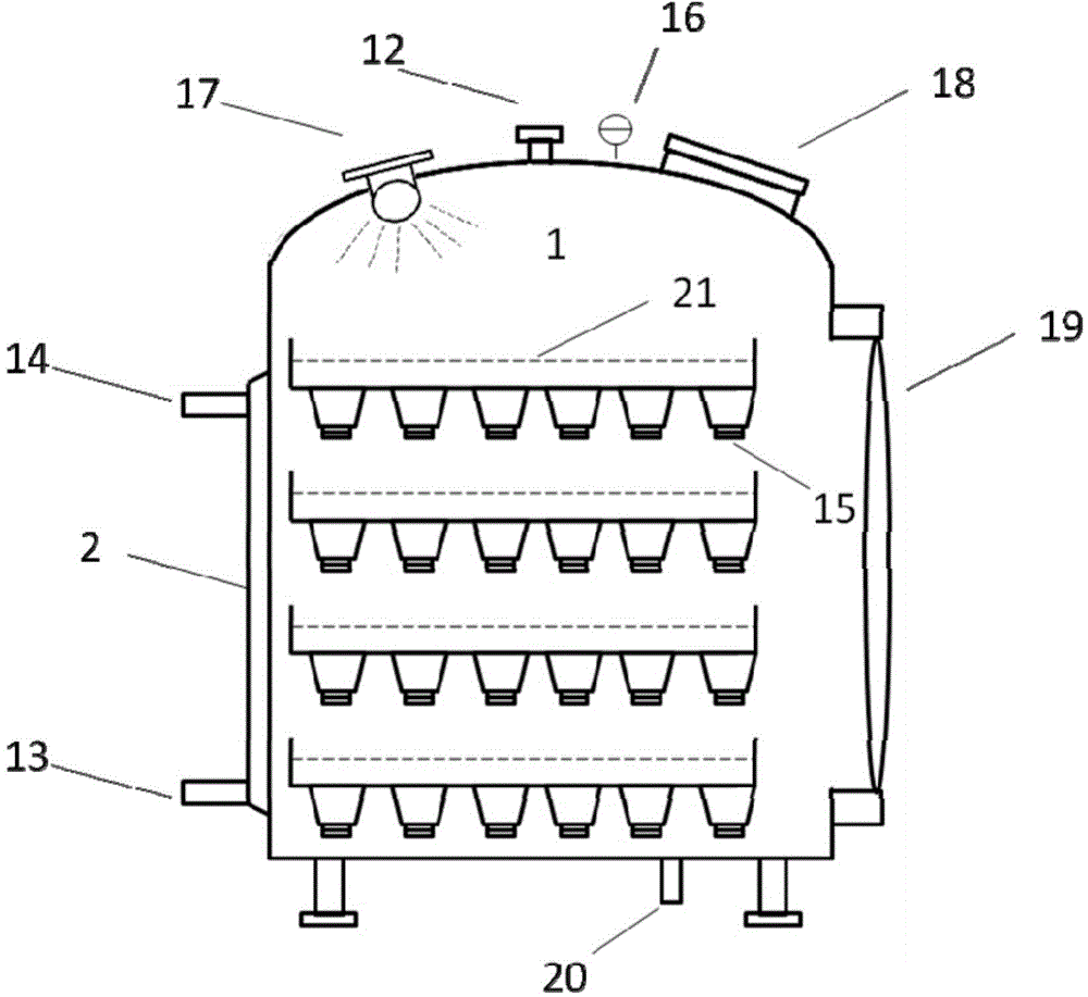
[0098] A multi-layer vacuum ultrasonic drying equipment, such as image 3 As shown, it includes the following structures: drying chamber 1, cooling jacket layer 2, vacuum control system, ultrasonic control system, cyclic refrigeration control system, air extraction port 12, circulating refrigerating liquid inlet 13, circulating refrigerating liquid outlet 14, ultrasonic transducer 15. Vacuum gauge 16, lighting equipment 17, viewing window 18, side door 19, sewage outlet 20 and material tank 21; material tank 21 is distributed in multiple layers in the drying chamber; cooling jacket layer 2 surrounds the drying chamber; sewage outlet 20 is located The bottom of the drying chamber 1; the bottom of each material tank 21 is uniformly provided with several (at least one) ultrasonic transducers 15, and the material tank 21 and the ultrasonic transducer 15 are controlled by the ultrasonic control system; 12 Extract the gas in the drying chamber 1; the circulating refrigerating liquid...


PUM


Abstract

The invention provides vacuum pulsation ultrasonic drying equipment, which comprises a drying room, an air supply system, a pulsation system, a circulating cooling control system, a vacuum control system, an ultrasonic control system, an ultrasonic transducer and the like. According to the equipment, by coupling the cavitation effect, the mechanical effect, the heat effect and the like of ultrasonic waves with vacuum pulsation, high-efficiency rapidly drying of a material is realized. The equipment is suitable for rapidly drying foodstuffs, medicines and biological materials, is especially suitable for drying high-viscosity thermosensitive natural products, and has the advantages that the energy consumption is saved, the drying time is shortened, the physical and chemical properties of the products are kept, and the like.

Description

technical field [0001] The invention relates to a drying device, which belongs to the field of biochemical equipment. Background technique [0002] Drying is one of the main production links in chemical, food, pharmaceutical and other industries, and it is also an energy-consuming link. In current production, vacuum drying, spray drying, and freeze drying are generally used for drying. Among them, spray drying and freeze drying have problems such as expensive equipment and high production costs. However, the existing vacuum drying requires long drying time, high energy consumption, and low production efficiency. shortcoming. [0003] For heat-sensitive plant natural products, heating and drying will cause the structure of these active ingredients to break down and decompose, reduce their activity, or even lose their activity. Especially for heat-sensitive and high-viscosity materials, drying is more difficult. [0004] Freeze-drying can well maintain the biological activit...

Claims


Application Information

Patent Timeline
IPC IPC(8): F26B9/06F26B5/02F26B5/04
Inventor 赵兵赵庆生
Owner INST OF PROCESS ENG CHINESE ACAD OF SCI
Why Eureka
Try Eureka