Multi-chip laminating type packaging structure and packaging method thereof
A packaging structure and packaging method technology, applied in the direction of semiconductor/solid-state device components, semiconductor devices, electrical components, etc., can solve the problems affecting the performance of the finished device, large volume, increased resistance and thermal resistance, etc., to achieve conduction loss and switching. The effect of reduced losses, better performance, and enhanced heat dissipation efficiency
- Summary
- Abstract
- Description
- Claims
- Application Information
AI Technical Summary
Problems solved by technology
Method used
Image
Examples
Embodiment 1
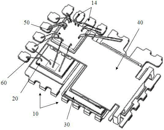
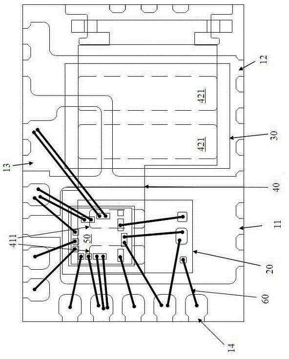
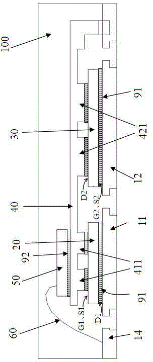
[0067] Cooperate see Figure 1A~Figure 1C As shown, in the present invention, two MOSFET chips of the same type (two N-type or two P-type) are used as high-end MOSFET chips (referred to as HS chips 20 for short) and low-end MOSFET chips (referred to as LS chips 30 for short). A controller chip (abbreviated as IC chip 50) is stacked on the same plane where the two MOSFET chips are located through a connecting sheet 40, and the IC chip 50 is connected to the corresponding electrodes of the LS chip 30 and the HS chip 20 and After the pins 14 are connected, they are packaged in the same plastic package 100 to form a DC-DC converter.
[0068] The HS chip 20 and the LS chip 30 are respectively provided with a source and a gate on the front of the chip, and a drain is provided on the back of the chip; wherein, the gate G1 of the HS chip 20 and the gate G2 of the LS chip 30 are both It is connected with the control pole on the IC chip 50; the drain D1 of the HS chip 20 is connected t...
Embodiment 2
[0094] Figure 4A~Figure 4G It shows the schematic structure in each step of chip packaging in this embodiment, Figure 5 The flow of the encapsulation method in this embodiment is shown. Wherein, the structure of this embodiment is briefly described as follows, that is, a lead frame 10 ( FIG. 4A ) is provided, including a first loading stage 11, which is used to fixedly connect the HS chip 20 and form an electrical connection with the back drain D1 ( Figure 4B ); also includes a second carrier stage, which is provided with a first part 12 and a second part 13, which are used to fix and connect the flipped package LS chip 30 and form an electrical connection with the source S2 and the gate G2 on the front side respectively ( Figure 4C ). A connecting piece 40 is conductively connected on the HS chip 20 and the LS chip 30, so that the high-side connection portion 41 of the connecting piece 40 is electrically connected to the source S1 on the front side of the HS chip 20, an...
Embodiment 3
[0098] Figure 6A ~ Figure 6G It shows the schematic structure in each step of chip packaging in this embodiment, Figure 7The flow of the encapsulation method in this embodiment is shown. Among them, the structure of this embodiment is briefly described as follows, that is, a lead frame 10 ( FIG. 6A ) is provided, including a first loading stage 11, which is used for fixedly connecting the HS chip 20 and forming an electrical connection with the back drain D1 ( Figure 6B ); also includes a second carrier stage, which is provided with a first part 12 and a second part 13, which are used to fix and connect the flipped package LS chip 30 and form an electrical connection with the source S2 and the gate G2 on the front side respectively ( Figure 6C ). A connecting piece 40 is conductively connected on the HS chip 20 and the LS chip 30, so that the high-side connection portion 41 of the connecting piece 40 is electrically connected to the source S1 on the front side of the HS ...
PUM
 Abstract
Description
Claims
Application Information
 - R&D
- Intellectual Property
- Life Sciences
- Materials
- Tech Scout
- Unparalleled Data Quality
- Higher Quality Content
- 60% Fewer Hallucinations
Browse by: Latest US Patents, China's latest patents, Technical Efficacy Thesaurus, Application Domain, Technology Topic, Popular Technical Reports.
© 2025 PatSnap. All rights reserved.Legal|Privacy policy|Modern Slavery Act Transparency Statement|Sitemap|About US| Contact US: help@patsnap.com


