Split stator of permanent magnet motor and manufacturing method of split stator

A technology of split stator and permanent magnet motor, which is applied in the manufacture of stator/rotor body, magnetic circuit, electrical components, etc., can solve the problems of difficulty in offline production of stator core manufacturing process, unfavorable long-term reliable operation, and high manufacturing cost. Simple and feasible maintenance, simple offline and assembly processes, and simple manufacturing and assembly processes

Inactive Publication Date: 2015-06-03
BEIJING RES INST OF PRECISE MECHATRONICS CONTROLS
View PDF5 Cites 3 Cited by
  • Summary
  • Abstract
  • Description
  • Claims
  • Application Information

AI Technical Summary

Problems solved by technology

However, in environments with extremely strict requirements on space dimensions, such as aerospace, petroleum industry and other fields, there are strict requirements on radial and axial dimensions, and permanent magnet motors can only use slender structures; under such requirements,

Method used


Image

  • Split stator of permanent magnet motor and manufacturing method of split stator
  • Split stator of permanent magnet motor and manufacturing method of split stator
  • Split stator of permanent magnet motor and manufacturing method of split stator

Examples


Example Embodiment

[0024] Example 1:

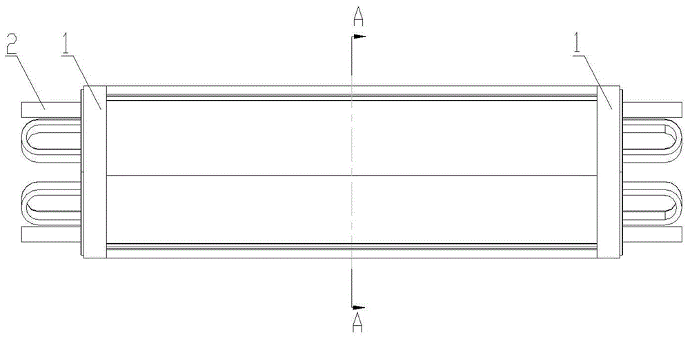
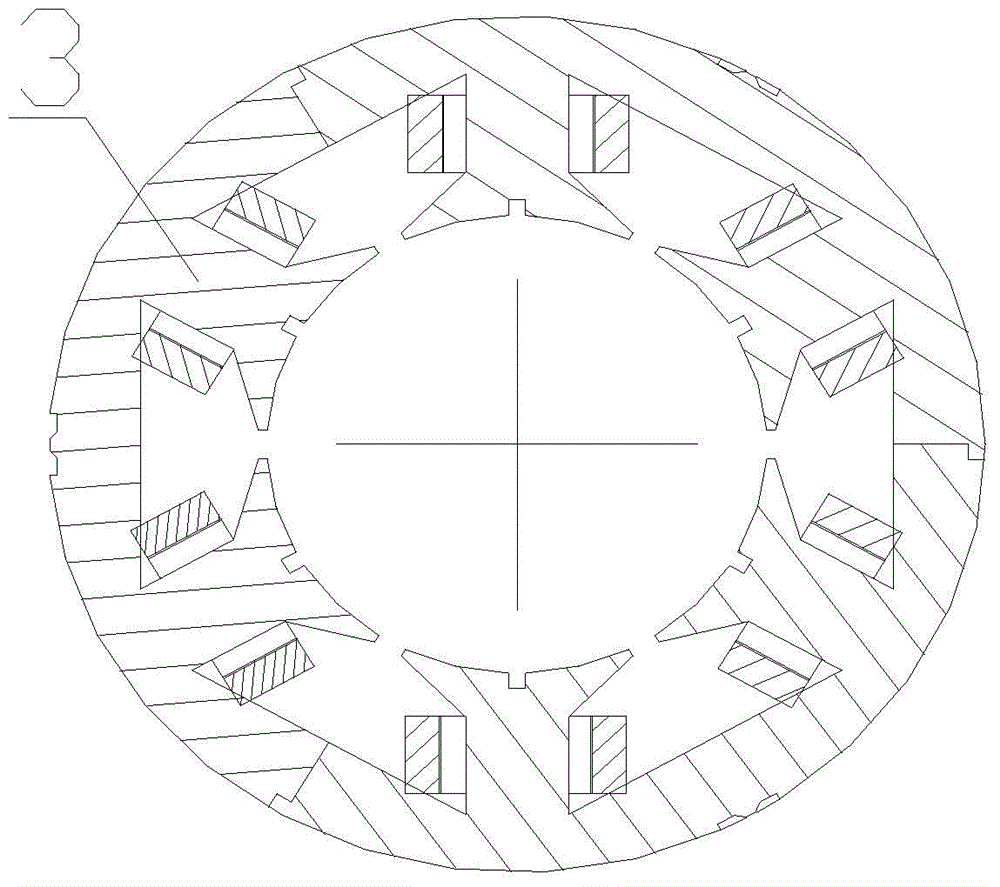
[0025] A split stator of a permanent magnet motor, comprising a split stator core 3 and a coil 2, the coil 2 is wound inside the split stator core 3, and a fastening ring 1, the split stator core 3 is composed of at least three Each petal is assembled with complete teeth, complete slots and half slots; the stator core is tightened by the fastening ring 1; the split stator of the permanent magnet motor is set as a cylinder whose bottom circle diameter is smaller than the length shape.

Example Embodiment

[0026] Example 2:

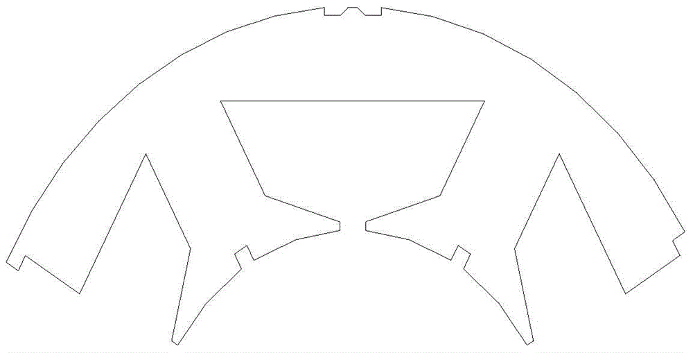
[0027] A split stator of a permanent magnet motor, similar to Embodiment 1, the difference is that the split stator core 3 is composed of three lobes, each lobe is provided with two complete teeth, a complete slot and two half slot; the outside of each lobe of the split stator core 3 is set as an arc-shaped outer circumference of one-third of the circumference, and its inner side is set as an arc-shaped inner circumference of one-third of the circumference concentric with it, and the outer The cross-section formed by the combination of the circumference and the inner circumference is fan-shaped; the outer circumference of each lobe of the split stator core 3 is provided with an inverted "concave" notch; each lobe of the split stator core 3 One end of the outer circumference is provided with an assembly boss, and the other end is provided with a matching assembly groove; the core teeth are provided with a groove at the end of the inner circumference.

Example Embodiment

[0028] Example 3:

[0029] A split stator of a permanent magnet motor is similar to Embodiment 2, the difference is that the number of fastening rings 1 is two, which are respectively arranged at the two ends of the split stator core 3 . The aspect ratio of the split stator of the permanent magnet motor, that is, the ratio of the length to the diameter of the bottom circle, is 6:1.


PUM


Abstract

The invention relates to a split stator of a permanent magnet motor. The split stator of the permanent magnet motor comprises a split stator core and a coil, wherein the coil is wound in the split stator core. The split stator of the permanent magnet motor further comprises fastening rings. The split stator core consists of at least three pieces through assembling, and each piece thereon is provided with complete teeth, a complete groove and half grooves; the stator core is tightly hooped through the fastening rings; the split stator of the permanent magnet motor is arranged to be of the shape of a cylinder of which the diameter of a base circle is smaller than the length. The split stator of the permanent magnet motor can solve the problems that the coil winding in the manufacturing process of the traditional stator core is difficult, the end portion of a winding is long, the manufacturing cost is high, the amount of heat produced by a coil is great, and the motor efficiency is low and it is not beneficial to long-time reliable operation, and can be widely applied to permanent magnet brushless direct-current motors or permanent magnet synchronous motors; the manufacturing and assembling process of the split stator of the permanent magnet motor is simple, the structure is compact, the tooth groove torque is small, and the end portion of the winding is short; the resistance is small, the heat loss is small, the efficiency is high, the maintenance is convenient to perform, and the operation is reliable.

Description

technical field [0001] The invention belongs to the technical field of motors, and relates to a permanent magnet motor split stator, in particular to a permanent magnet motor split stator and its Manufacturing method. Background technique [0002] The permanent magnet motor is an electromagnetic device that uses the magnetic field generated by the permanent magnet as the medium to realize electromechanical energy conversion according to the law of electromagnetic induction. Compared with the traditional electric excitation motor, the permanent magnet motor has simple structure, high reliability and small size. , light weight, high efficiency, low temperature rise, etc., are widely used in various fields of national production; with the development of high-performance permanent magnet materials, permanent magnet motors gradually replace traditional electric excitation motors with their superior performance. It is widely used in industry, aerospace, electric power and other f...

Claims


Application Information

Patent Timeline
IPC IPC(8): H02K1/12H02K15/02
CPCH02K1/148H02K15/02H02K2213/03
Inventor 张达秦二卫白玉新张朝阳胡林
Owner BEIJING RES INST OF PRECISE MECHATRONICS CONTROLS
Why Eureka
Try Eureka