Waste catalyst mud water dehydration treatment equipment and waste catalyst mud water dehydration treatment method

A waste catalyst and treatment equipment technology, which is applied in water/sludge/sewage treatment, sludge treatment, dehydration/drying/thickened sludge treatment, etc., can solve the problems of high cost and poor treatment effect of waste catalyst muddy water, etc. Achieve the effects of small footprint, clean production waste reduction treatment, and high degree of automation

Active Publication Date: 2015-06-10
NANJING BALANCE ENVIRONMENTAL TECH CO LTD
View PDF8 Cites 4 Cited by
  • Summary
  • Abstract
  • Description
  • Claims
  • Application Information

AI Technical Summary

Problems solved by technology

[0004] Aiming at the shortcomings of the existing technology in treating waste catalyst muddy water, the present invention proposes a waste catalyst muddy water dehydration treatment equipment and method, which combin

Method used


Image

  • Waste catalyst mud water dehydration treatment equipment and waste catalyst mud water dehydration treatment method
  • Waste catalyst mud water dehydration treatment equipment and waste catalyst mud water dehydration treatment method

Examples


Example Embodiment

[0038] Example 1

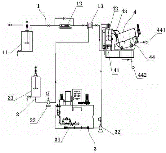
[0039] Such as figure 1 As shown, a waste catalyst sludge dehydration treatment equipment includes a sludge conveying device 1, a complexing agent dosing device 2, a flocculant dosing device 3, and a snail dehydration device 4, the complexing agent dosing device includes a complexing device A mixture preparation tank 21 and a complexing agent dosing pump 22. The flocculant dosing device includes an automatic flocculant foaming device 31 and a flocculant dosing pump 32. The snail dewatering device includes a flocculation mixing tank 41 and a stirring The device 42, the throwing device 43 and the screw stacker main body 44. The sludge conveying device includes an intermediate stirring tank 11, a sludge conveying pump 12 and a pipeline mixer 13, and the waste catalyst sludge from the bottom of the wastewater clarifier is discharged into the The intermediate stirring tank, after being stirred by the intermediate stirring tank, is added to the pipeline mixer by the ...

Example Embodiment

[0056] Example 2

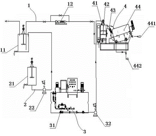
[0057] Such as figure 2 As shown, a waste catalyst sludge dehydration treatment equipment includes a sludge conveying device 1, a complexing agent dosing device 2, a flocculant dosing device 3, and a snail dehydration device 4, the complexing agent dosing device includes a complexing device A mixture preparation tank 21 and a complexing agent dosing pump 22. The flocculant dosing device includes an automatic flocculant foaming device 31 and a flocculant dosing pump 32. The snail dewatering device includes a flocculation mixing tank 41 and a stirring The device 42, the throwing device 43 and the screw stacker main body 44. The sludge conveying device includes an intermediate stirring tank 11 and a sludge conveying pump 12. The waste catalyst sludge from the bottom of the clarification tank is discharged into the intermediate stirring tank, and The mixture dosing pump adds the complexing agent selected in the complexing agent preparation tank to the intermediat...


PUM


Abstract

The invention discloses waste catalyst mud water dehydration treatment equipment and a waste catalyst mud water dehydration treatment method, and belongs to the technical field of solid-liquid separation in environmental engineering. The equipment comprises a sludge conveyer device, a complexing agent feeding device, a flocculating agent feeding device and a coiled dehydration device. The technique method comprises the following steps: conveying waste catalyst mud water; adding a complexing agent and a flocculating agent; and carrying out mixing reaction, and coiled dehydration. The moisture content of the waste catalyst mud water can be reduced to about 50% from 99.5% once by only adding the compounded medicine and combining with a coiled dehydration manner. According to the technique and the equipment, deep dehydration is carried out on the waste catalyst mud water; the treatment cost of the sewage is reduced; and a good way is provided for reduction treatment of a waste catalyst. Compared with an existing dehydration technology of combining filtration with a vacuum belt dehydrator, the technology is not easy to block, small in floor area, simple to operate, high in automatic degree and low in operation cost, and does not generate secondary pollution.

Description

technical field [0001] The invention relates to a method for dehydrating waste catalyst muddy water and treatment equipment thereof, in particular to a waste catalyst muddy water treatment method which combines high-efficiency compound medicament with stacking screw dehydration. Background technique [0002] The catalytic cracking unit in the refinery is one of the main processing units for heavy oil processing. Catalyst consumption and replacement is one of the main operating characteristics of the unit. The normal fresh catalyst consumption is 0.6-1.4kg / t raw material, while the catalyst consumption of 0.3-0.6 kg / t raw material It is lost to the atmosphere through the chimney. As the national environmental protection regulations become more and more strict, the emission indicators of SO2, NOX and dust content in the chimney of the catalytic device are strictly controlled. Flue gas desulfurization and denitrification technologies are being used at home and abroad to meet t...

Claims


Application Information

Patent Timeline
IPC IPC(8): C02F11/14C02F11/12
CPCC02F11/125C02F11/14
Inventor 荆建波张继荣
Owner NANJING BALANCE ENVIRONMENTAL TECH CO LTD
Why Eureka
Try Eureka