Preparation method for spherical cavity equipped polymer fiber and special microfluidic chip

A microfluidic chip and polymer technology, which is applied in fiber processing, fiber chemical characteristics, rayon manufacturing, etc., can solve problems such as difficult preparation of fiber materials, and achieve the effect of flexible polymerization methods and various types

Active Publication Date: 2015-06-10
DALIAN INST OF CHEM PHYSICS CHINESE ACAD OF SCI
View PDF8 Cites 20 Cited by
  • Summary
  • Abstract
  • Description
  • Claims
  • Application Information

AI Technical Summary

Problems solved by technology

However, as far as polymer fibers are concerned, due to the limitation of processing method...

Method used


Image

  • Preparation method for spherical cavity equipped polymer fiber and special microfluidic chip
  • Preparation method for spherical cavity equipped polymer fiber and special microfluidic chip
  • Preparation method for spherical cavity equipped polymer fiber and special microfluidic chip

Examples


Embodiment 1

[0026] Embodiment 1: chip structure of the present invention

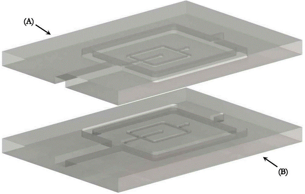
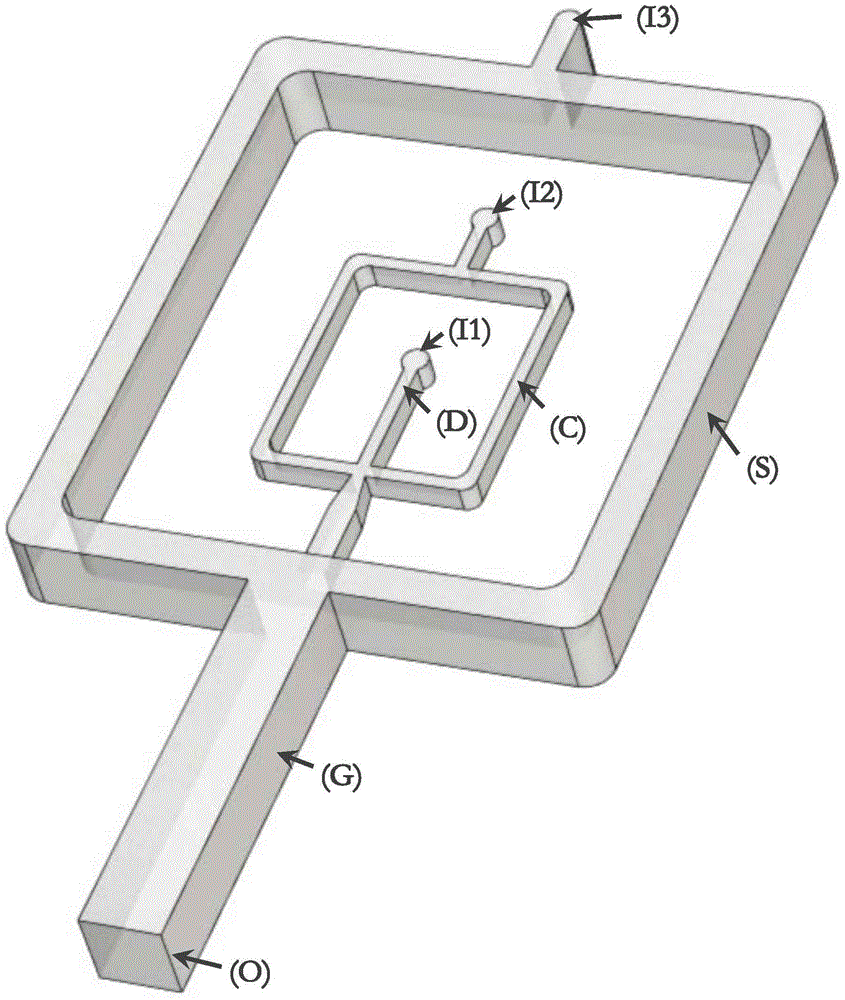
[0027] The microfluidic chip of the present invention is divided into two layers, the surfaces of the two layers of materials have channel structures, and the two channel structures are mirror-symmetrical, and the two-layer chip materials are sealed together when the two mirror-symmetrical channel structures overlap each other; wherein, The chip includes an inlet and a channel of a continuous phase solution, an inlet and a channel of a dispersed phase solution, an inlet and a channel of a sheath flow solution, an entrainment channel structural unit, a spout structural unit, a polymer fiber generation channel, and a product collection outlet.

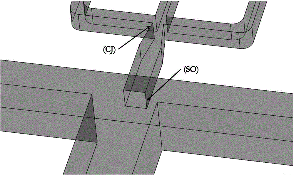
[0028] The entrainment channel structure is located upstream of the spout structure, and is the intersection of the continuous phase solution channel and the dispersed phase solution channel, and is in the shape of a cross.

[0029] The nozzle structural unit is located downs...

Embodiment 2

[0032] Formation of Monodisperse Droplets and Sheath Flow Patterns Using the Chip of the Invention

[0033] Using a syringe pump, inject non-polar solvent X (dispersed phase solution), polar solvent Y solution (continuous phase solution), and non-polar solvent Z (sheath flow solution) into the microfluidic chip through their respective inlets. The dispersed phase solution channel, the continuous phase solution channel and the sheath flow solution channel. Adjust the flow rate of each fluid to an appropriate range. It can be observed under a microscope that when the solvent X flows through the entrainment channel structural unit, it is dispersed into droplets by the solvent Y, and is continuously carried to the downstream nozzle structural unit by the solvent Y. When the solvent Y flows from the continuous phase solution channel through the nozzle structural unit into the polymer fiber to form a channel, it is wrapped by the solvent Z that also flows into this channel to form ...


PUM


Abstract

The invention relates to a preparation method for a spherical cavity equipped polymer fiber and a special microfluidic chip. With the chip and the method, polymer fiber with a diameter ranging from micron level to millimeter level can be prepared. Spacing and size controllable spherical cavities can continuously be formed in the polymer fiber, and various inclusions can be loaded in the cavities. The method combines a droplet microfluidic technology and a spinning microfluidic technology, utilizes the droplet microfluidic technology to disperse a volatile liquid uniformly in the continuous flow of a polymer monomer solution in the form of droplets, and utilizes the spinning microfluidic technology to form polymer fiber and arrange the droplets therein orderly. The droplet solution is removed from solidified polymer fiber by means of its volatilization characteristic so as to form the spherical cavities with uniform and controllable size and adjustable spacing. The substances added into the droplets in advance can be loaded into the fiber cavities, and the material can be endowed with flexible performance so as to be expected for application in wide fields.

Description

technical field [0001] The invention belongs to the intersecting field of new material technology and microfluidic technology, and specifically relates to a method for preparing polymer fibers with spherical cavities and a special microfluidic chip. Background technique [0002] The invention relies on microfluidic technology. Microfluidic chip (microfluidic chip), also known as lab on a chip, refers to the integration of the basic operating units of conventional laboratories on a chip of several square centimeters (or even smaller), forming a network of microchannels. , a technology that uses controllable fluid throughout the entire system to replace various functions of conventional laboratories. Droplet microfluidics is an important branch of microfluidic chip technology. It utilizes two-phase flow to form monodisperse water droplets or oil droplets in T-shaped or pinched microfluidic channels. Monodisperse droplets provide a strong support for high-throughput microana...

Claims


Application Information

Patent Timeline
IPC IPC(8): D01F9/04D01F1/08D01D5/24D01D5/38
Inventor 秦建华于跃
Owner DALIAN INST OF CHEM PHYSICS CHINESE ACAD OF SCI
Why Eureka
Try Eureka