Powder metallurgy compound cam and manufacturing method thereof
A composite cam and powder metallurgy technology, applied in the cam field, can solve the problems of uneven roundness of 2-2 inner lining, increase cost, etc., and achieve uniform hardness distribution, good inner hole dimensional accuracy, and good wear resistance.
- Summary
- Abstract
- Description
- Claims
- Application Information
AI Technical Summary
Problems solved by technology
Method used
Image
Examples
Embodiment 1
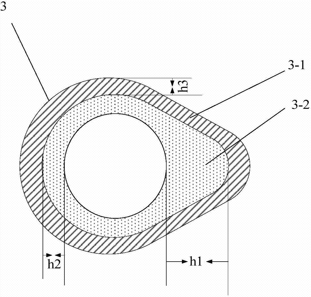
[0050] This embodiment provides a powder metallurgy composite cam, image 3 Its schematic top view is shown. Such as image 3 As shown, the powder metallurgy composite cam 3 includes a cam plate 3-1 and an inner lining 3-2. The shown cam piece 3-1 is combined with the inner liner 3-2.
[0051]In the application of the cam, the cam plate 3-1 of the cam needs to work together with the driving mechanism such as the tappet of the engine, which requires the outer edge of the cam plate 3-1 to have a higher hardness, so in this embodiment the cam plate 3 -1 is made of the first material by powder metallurgy. The first material is composed of a host material including iron, phosphorus, and carbon, and an additive material, and the additive material is any one or a combination of elements such as chromium, molybdenum, tungsten, copper, nickel, silicon, and manganese. The composition and mass percentage of the first material are 0-20% of chromium, 0-10% of molybdenum, 0-5% of tungst...
Embodiment 2
[0063] This embodiment provides another powder metallurgy composite cam, Figure 5 Its schematic top view is shown. Such as Figure 5 As shown, the powder metallurgy composite cam 4 includes a cam piece 4-1 and an inner lining 4-2. The shown cam piece 4-1 is combined with the inner lining 4-2.
[0064] In the application of the cam, the cam plate 4-1 of the cam needs to work together with the driving mechanism such as the tappet of the engine, which requires the outer edge of the cam plate 4-1 to have a higher hardness, so in this embodiment, the cam plate 4-1 -1 is made of the first material. The first material is composed of a host material including iron, phosphorus, and carbon, and an additive material, and the additive material is any one or a combination of elements such as chromium, molybdenum, tungsten, copper, nickel, silicon, and manganese. The composition and mass percentage of the first material are 0-20% of chromium, 0-10% of molybdenum, 0-5% of tungsten, 0-15...
Embodiment 3
[0073] This embodiment provides the preparation method of the powder metallurgy composite cam in the first embodiment and the second embodiment.
[0074] The preparation method includes the following steps.
[0075] Firstly, the cam piece green body and the lining green body are manufactured respectively, the raw material of the cam piece green body is a first material, and the first material is composed of a main body material including iron, phosphorus and carbon and an added material, and the added The material is any one or combination of chromium, molybdenum, tungsten, copper, nickel, silicon, manganese and other elements. The composition and mass percentage of the first material are 0-20% of chromium, 0-10% of molybdenum, 0-5% of tungsten, 0-15% of copper, 0-8% of nickel, and 0% of silicon. ~3%, manganese is 0~3%, phosphorus is 0.1~1%, carbon is 0.1~5%, and the rest is iron. In a preferred manner, the composition and mass percentage of the first material are 3-6% of chro...
PUM
| Property | Measurement | Unit |
|---|---|---|
| Depth | aaaaa | aaaaa |
| Density | aaaaa | aaaaa |
Abstract
Description
Claims
Application Information
 - R&D
- Intellectual Property
- Life Sciences
- Materials
- Tech Scout
- Unparalleled Data Quality
- Higher Quality Content
- 60% Fewer Hallucinations
Browse by: Latest US Patents, China's latest patents, Technical Efficacy Thesaurus, Application Domain, Technology Topic, Popular Technical Reports.
© 2025 PatSnap. All rights reserved.Legal|Privacy policy|Modern Slavery Act Transparency Statement|Sitemap|About US| Contact US: help@patsnap.com


