
Energy-storage type leapfrog-simulation robot

A robot, energy storage technology, applied in the field of jumping robots, can solve the problems of not being able to play their respective advantages, slow speed of servo motors, high spring power density, etc., to optimize the leg structure, improve the degree of bionics, and the effect of strong jumping explosive force.

Active Publication Date: 2015-06-17
HARBIN ENG UNIV
View PDF10 Cites 16 Cited by
  • Summary
  • Abstract
  • Description
  • Claims
  • Application Information

AI Technical Summary

Problems solved by technology

The legs of the robot imitate the hind legs of the frog very well, and its feet are also equipped with elastic elements, but after it takes off, it only uses the foot elastic elements and the spring of the hip joint to cushion, the cushioning effect is not very good, and the hip joint The spring needs to be stretched for a long distance before it can be released, which affects the take-off efficiency
[0010] The patent application No. 201310553698.5 proposes a five-joint imitation frog jumping robot, which uses a servo motor to drive the rear legs with springs to jump. Due to the high power density and fast speed of the spring, the slow speed and low power density of the servo motor, the two Coupling cannot give full play to their respective advantages; the soles of the hind legs adopt the form of stretching and pushing rods, which is different from the rotation of the soles of biological movements, and the degree of bionics is not high

Method used


Image

  • Energy-storage type leapfrog-simulation robot
  • Energy-storage type leapfrog-simulation robot
  • Energy-storage type leapfrog-simulation robot

Examples


Embodiment Construction

[0024] The present invention is described in more detail below in conjunction with accompanying drawing example:

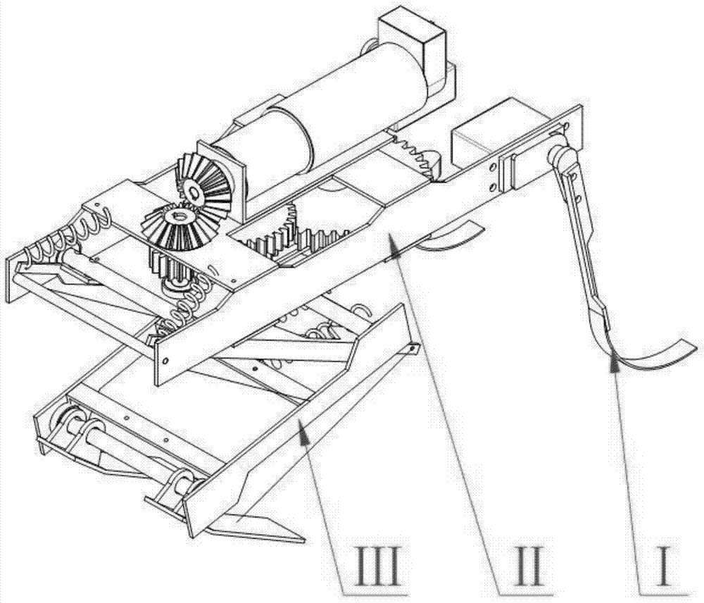
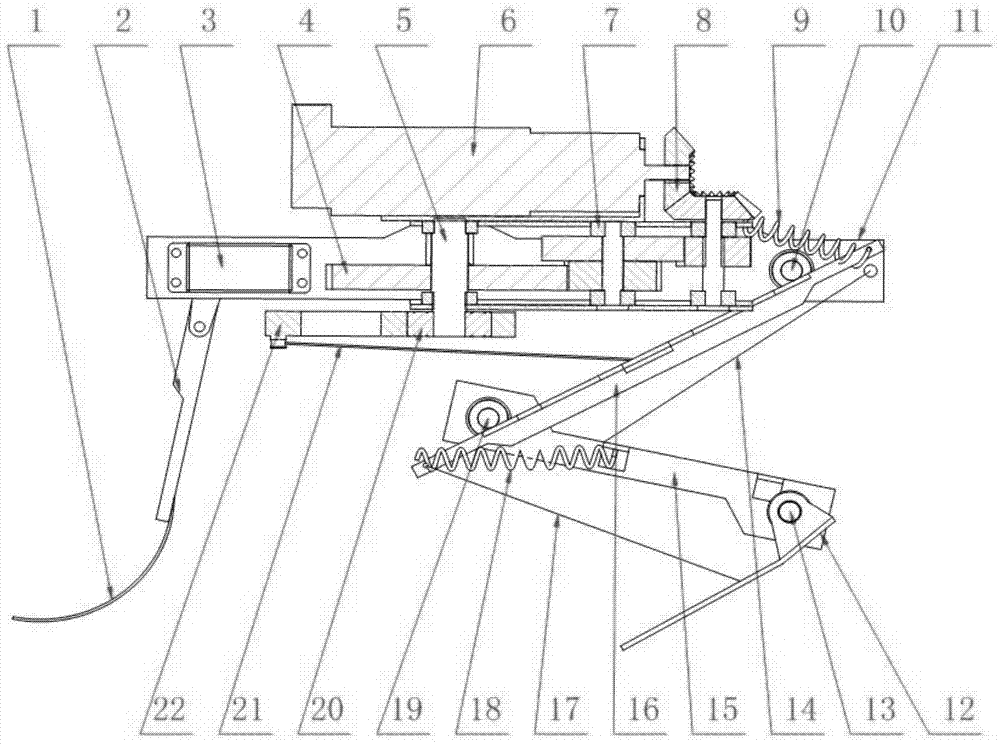
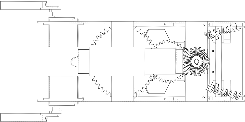
[0025] combine Figure 1~5 , the entire energy-storage frog-like robot is mainly composed of three parts: forelimb Ⅰ, torso Ⅱ, and hindlimb Ⅲ; the entire robot specifically includes:

[0026] C-shaped flexible forefoot 1, forelimb thigh 2, steering gear 3, secondary gear reducer 4, crank shaft 5, servo motor 6, deep groove ball bearing 7, bevel gear 8, hip joint energy storage spring 9, hip joint shaft 10. Trunk structure aluminum plate 11, hind limb sole 12, ankle joint axis 13, calf linkage cable 14, hind limb calf 15, hind limb thigh 16, sole linkage cable 17, knee joint energy storage spring 18, knee joint axis 19, one-way Bearing 20, hindlimb driving cable 21, rotary crank 22.

[0027] The assembly relationship of the entire energy-storage frog-like robot is as follows: the entire torso II is a frame composed of aluminum plates connected by screws; the serv...


PUM


Abstract

The invention aims to provide an energy-storage type leapfrog-simulation robot. The energy-storage type leapfrog-simulation robot comprises fore limbs, a body and hind limbs, wherein a servo motor drives a rotating crank to rotate, the rotating crank pulls hind legs to swing forwards through an inhaul cable so that energy storage can be performed, when the rotating crank rotates by 180 degrees, the force, acting on the crank through the inhaul cable, of hind limb energy storage springs is in the opposite direction, a one-way bearing is separated from a shaft, the acting force disappears, the hind legs are not constrained, the whole robot is pushed to complete the jumping task through the acting force of the springs, the hind leg springs return to the original length after jumping, the motor continues to dive the crank to rotate, and the hind legs are pulled to complete the leg retracting action after jumping; when the robot falls to the ground, the contact angle between each fore limb and the ground is adjusted by a steering engine, and ground impact is relieved through C-shaped flexible foot soles. Driving mechanisms and executing mechanisms of the fore limbs and the hind limbs are reasonably arranged, the utilization rate of driving elements of the robot is increased, the bionic degree of the robot is improved, the jumping capacity of the robot is enhanced, and the flexible effect and the buffering effect of the mechanical structure of the robot are improved.

Description

technical field [0001] The invention relates to a robot, specifically a jumping robot. Background technique [0002] The current field of robot research has moved from fixed-point operations in structured environments to autonomous operations in non-structural environments such as aerospace, ocean development, underwater underground pipelines, and medical rescue. Robots of the future will work for humans in unpredictable and complex environments. People require robots not only to adapt to the original structured and known environment, but also to adapt to the unstructured and unknown environment in the future development, which requires the robot to have strong autonomous movement ability, survivability and high movement flexibility. [0003] Mobility performance is the key capability of robots in many applications in the future. In order to complete tasks, robots are often required to penetrate into restricted areas where humans cannot enter for reconnaissance, detection,...

Claims


Application Information

Patent Timeline
IPC IPC(8): B62D57/032
CPCB62D57/02
Inventor 胡胜海芦晨军郭春阳孙军超祁松谢婷婷张红万济民田飞鸿费宇霆
Owner HARBIN ENG UNIV
Learn More