Cooling fin

A heat sink and dispersant technology, applied in the direction of conjugated diene coatings, epoxy resin coatings, polyurea/polyurethane coatings, etc., can solve the problems of poor heat dissipation and poor thermal conductivity, and achieve lower temperature and production The effect of low cost and improved heat dissipation speed

Active Publication Date: 2015-06-17
东莞市闻誉实业有限公司
View PDF8 Cites 23 Cited by
  • Summary
  • Abstract
  • Description
  • Claims
  • Application Information

AI Technical Summary

Problems solved by technology

[0007] However, the above disclosed patents still have defects su

Method used


Image

  • Cooling fin
  • Cooling fin

Examples


Embodiment 1

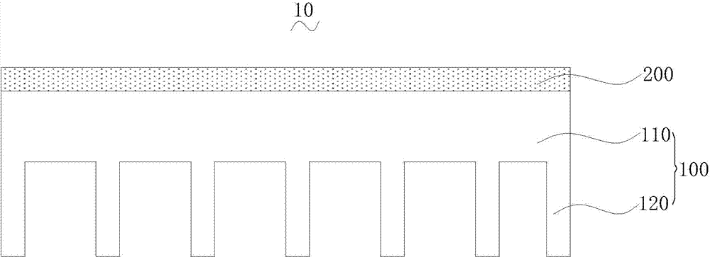
[0094] 1. Production of substrate:

[0095] According to parts by weight: aluminum: 77.8 parts; zinc: 12 parts; copper: 9 parts; boron: 0.3 parts; nickel: 0.05 parts; manganese: 0.5 parts; Heating to 800°C to 850°C.

[0096] After melting into molten aluminum alloy, reduce the temperature in the furnace to 710°C-750°C, add refining agent to the molten aluminum alloy, refine for 15-25 minutes, and then carry out slag removal.

[0097] For example, the refining agent is evenly blown into the aluminum alloy liquid through a powder spraying tank for refining. During refining, the nitrogen pressure is 0.2MPa, and the nitrogen purity is greater than 99 parts. For another example, after refining for 15 to 25 minutes, remove the scum on the surface of the aluminum alloy liquid.

[0098] Control the temperature in the furnace at 750°C to 770°C, and let it stand for 25 to 35 minutes to degas and remove slag.

[0099] Specifically, after the standing is completed, the aluminum alloy l...

Embodiment 2

[0109] 1. Production of substrate:

[0110] According to parts by weight: aluminum: 69.7 parts; zinc: 18 parts; copper: 10.5 parts; boron: 0.7 parts; nickel: 0.05 parts; manganese: 1.0 parts; Heating to 800°C to 850°C.

[0111] After melting into molten aluminum alloy, reduce the temperature in the furnace to 710°C-750°C, add refining agent to the molten aluminum alloy, refine for 15-25 minutes, and then carry out slag removal.

[0112] For example, the refining agent is evenly blown into the aluminum alloy liquid through a powder spraying tank for refining. During refining, the nitrogen pressure is 0.2MPa, and the nitrogen purity is greater than 99 parts. For another example, after refining for 15 to 25 minutes, remove the scum on the surface of the aluminum alloy liquid.

[0113] Control the temperature in the furnace at 750°C to 770°C, and let it stand for 25 to 35 minutes to degas and remove slag.

[0114] For example, after the standing is completed, the aluminum alloy...

Embodiment 3

[0125] 1. Production of substrate:

[0126] According to parts by weight: aluminum: 72 parts; zinc: 15 parts; copper: 11 parts; boron: 0.35 parts; nickel: 0.3 parts; manganese: 1.2 parts; Heating to 800°C to 850°C.

[0127] After melting into molten aluminum alloy, reduce the temperature in the furnace to 710°C-750°C, add refining agent to the molten aluminum alloy, refine for 15-25 minutes, and then carry out slag removal.

[0128] For example, the refining agent is evenly blown into the aluminum alloy liquid through a powder spraying tank for refining. During refining, the nitrogen pressure is 0.2MPa, and the nitrogen purity is greater than 99 parts. For another example, after refining for 15 to 25 minutes, remove the scum on the surface of the aluminum alloy liquid.

[0129] Control the temperature in the furnace at 750°C to 770°C, and let it stand for 25 to 35 minutes to degas and remove slag.

[0130] Specifically, after the standing is completed, the aluminum alloy li...


PUM

PropertyMeasurementUnit
Thicknessaaaaaaaaaa
Thicknessaaaaaaaaaa
Thicknessaaaaaaaaaa

Abstract

The invention discloses a cooling fin. The cooling fin comprises a base plate and a coating, wherein the coating is arranged on the base plate and is prepared from graphene solutions; the graphene solutions comprise the following components in parts by weight: 5-15 parts of graphene, 20-70 parts of adhesives, 0.25-0.6 part of dispersing agent, 0.05-0.3 part of surfactant, and 0.5-5 parts of antifoaming agents. According to the cooling fin, the graphene coating is coated on the surface of the base plate; by utilizing the extremely-high heat conductivity of the graphene, the surface transmission of the heat energy can be quickly carried out along a graphene film, and the heat energy is quickly transmitted to the inside of the cooling fin, so that the time for transferring the heat to the cooling fin from a heat-conductive interface material or a heating device is shortened, the cooling speed of the cooling fin is improved, and the temperature of the cooling device is reduced. In addition, the cooling fin is simple in preparation process and relatively low in production cost.

Description

technical field [0001] The invention relates to the technical field of heat conducting materials, in particular to a heat sink. Background technique [0002] With the vigorous development of high technology, electronic products are becoming more and more intelligent and complex, the volume of electronic components tends to be miniaturized, and the density per unit area is also getting higher and higher. The direct impact of this situation is that electronic products generate more and more heat during operation. If there is no good heat dissipation method to remove the heat generated by the electrons, these excessively high temperatures will lead to electron ionization and thermal stress in the electronic components, resulting in a decrease in overall stability and shortening the life of the electronic components themselves. Therefore, how to remove these heats to avoid overheating of electronic components has always been a problem that cannot be ignored. [0003] At presen...

Claims


Application Information

Patent Timeline
IPC IPC(8): C09D163/10C09D127/16C09D175/04C09D109/06C09D133/20C09D7/12
CPCC08L2205/03C09D7/61C09D109/06C09D127/16C09D133/20C09D163/10C09D175/04C08L33/02C08L39/06C08K3/04C08L27/06C08L83/04C08L71/02C08L5/04C08L1/286C08L71/08C08L23/06C08K5/098
Inventor 叶伟炳
Owner 东莞市闻誉实业有限公司
Why Eureka
Try Eureka