
Microwave phase-locked thermal imaging system and method

A microwave phase-locking and thermal imaging technology, which is used in target detection, medical imaging, and non-destructive testing.

Active Publication Date: 2015-06-17
WUXI DOUBLE HORSE DRILLING TOOLS
View PDF7 Cites 21 Cited by
  • Summary
  • Abstract
  • Description
  • Claims
  • Application Information

AI Technical Summary

Problems solved by technology

Literature [3] provides a microwave thermal imaging detection system, which uses a function generator and a relay to control the switch of a commercial microwave oven, and intermittently heats the object to be inspected. The system integration is low, the function is simple, and it is not practical.
The existing microwave thermal imaging defect detection technology has the following shortcomings: 1) The defect detection method mainly relies on the original thermal image and transient temperature curve, which is susceptible to noise interference; 2) It is difficult to overcome the interference of uneven heating and surface emissivity; 3 ) Affected by the attenuation of the thermal wave signal, the detection depth is small

Method used


Image

  • Microwave phase-locked thermal imaging system and method
  • Microwave phase-locked thermal imaging system and method
  • Microwave phase-locked thermal imaging system and method

Examples


Embodiment Construction

[0057] The specific embodiments of the present invention are described below in conjunction with the accompanying drawings, so that those skilled in the art can better understand the present invention.

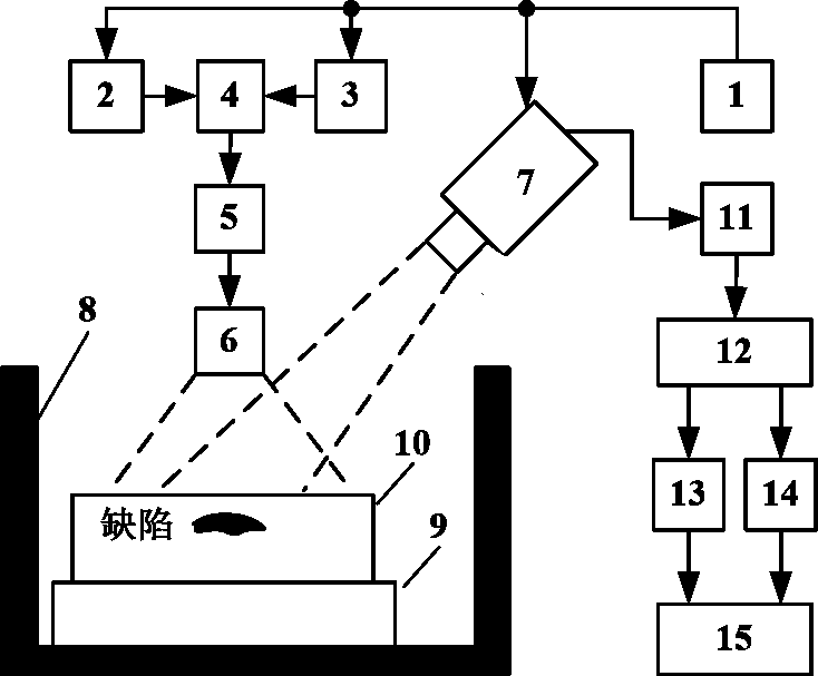
[0058] figure 1 It is a schematic diagram of a microwave phase-locked thermal imaging system, mainly including: control module 1, microwave generator 2, phase-locked signal generator 3, amplitude modulation device 4, power amplifier 5, antenna 6, thermal imager 7, microwave protection Device 8, platform 9, inspected object 10, computer 11, reference signal setting module 12, Fourier transform module-13, phase lock correlation module 14, imaging module 15, etc.

[0059] The specific implementation steps of a microwave lock-in thermal imaging method based on a microwave lock-in thermal imaging system are as follows:

[0060] 1) Place the inspected object 10 on the platform 9 in the microwave protection device 8; adjust the positions of the antenna 6 and the inspected object 10 so that ...


PUM


Abstract

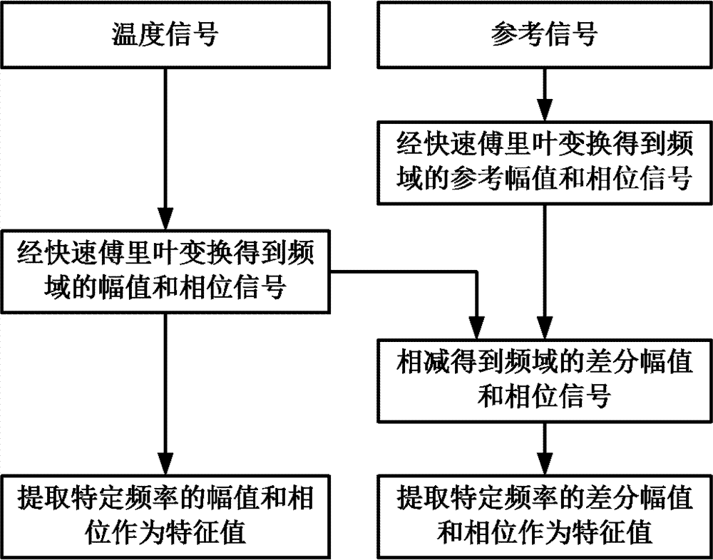
The invention discloses a microwave phase-locked thermal imaging system and method. The method comprises the following steps: periodically heating a detected object by adopting continuous microwaves subjected to amplitude modulation by a periodic phase-locked signal, generating thermal waves with periodic change inside the detected object, and recording a temperature signal with the periodic change on the surface of the detected object by adopting a thermal imager, wherein the temperature signal can reflect thermal wave abnormality caused by defects; setting a reference signal according to the phase-locked signal or a temperature signal without a defect area; performing fast Fourier transform on the temperature signal and the reference signal, and extracting the amplitude and the phase of specific frequency such as phase-locked frequency as characteristic values; performing phase-locked association on the temperature signal and the reference signal, and extracting the amplitude and the phase of the phase-locked frequency as characteristic values; and performing reconstruction imaging on the characteristic values of all pixel points of a detected area. The method and the system have the advantages of high signal to noise ratio, capacity of suppressing the emissivity change, large detection depth and the like and can be widely applied to the fields of nondestructive testing, medical imaging, target detection and the like.

Description

Technical field [0001] The invention belongs to the technical fields of non-destructive detection, target detection, medical imaging and the like, and particularly relates to a microwave thermal imaging detection, detection and imaging system and method. Background technique [0002] With the development of modern science and industrial technology, non-destructive testing technology has become a necessary means to ensure product quality and equipment operation safety. At present, the representative non-destructive testing technologies mainly include radiographic testing, ultrasonic testing, penetrant testing, magnetic particle testing, eddy current testing and thermal imaging testing. [0003] Thermal imaging detection technology uses a heat source to heat the inspected object, and uses a thermal imager to observe and record the temperature change information of the inspected object's surface, so as to detect and evaluate the surface and internal defects of the inspected object. T...

Claims


Application Information

Patent Timeline
IPC IPC(8): G01N25/72
Inventor 何赟泽杨瑞珍
Owner WUXI DOUBLE HORSE DRILLING TOOLS
Learn More