
Automotive liquefied natural gas cylinder

A technology of liquefied natural gas and gas cylinders, which is applied in the field of improvement of the structure of gas cylinders, can solve the problems of weak gas supply system, failure of self-pressurization equipment, failure of normal use, etc., to solve the inconvenience of use and safety hazards, and reduce the amount of welding deformation , The effect of increasing the heat conduction path

Inactive Publication Date: 2015-06-24
SHAANXI AUTOMOBILE GROUP +1
View PDF8 Cites 7 Cited by
  • Summary
  • Abstract
  • Description
  • Claims
  • Application Information

AI Technical Summary

Problems solved by technology

There are many deficiencies in the LNG cylinders for vehicles with self-pressurization structure: the gas supply of the self-pressurization system is unstable. The self-pressurization equipment has the risk of failure; the self-pressurization system is affected by the ambient temperature. When the filling pressure of the filling station is too low, the LNG cylinder with the self-pressurization equipment needs to wait for 15 to 30 hours after filling. Boosting in minutes; self-boosting equipment is inconvenient to operate, and the driver needs to operate it himself; the control of the self-boosting system cannot be automated, and the performance indicators required for the engine depend on the driver’s experience and operation; self-boosting equipment has potential safety hazards. Gas cylinders become the weakest link in the entire gas supply system after the addition of pressurized equipment, and affect other performances such as thermal insulation of gas cylinders
The existing gas cylinders all use the pressure inside the cylinder to make the liquefied natural gas flow out of the cylinder for use by the engine. However, in plateau areas, the external pressure itself is small, which makes the existing gas cylinders unable to discharge liquid, so that they cannot be used normally.

Method used


Image

  • Automotive liquefied natural gas cylinder
  • Automotive liquefied natural gas cylinder
  • Automotive liquefied natural gas cylinder

Examples


Embodiment Construction

[0037] The present invention will be further described below in conjunction with the accompanying drawings.

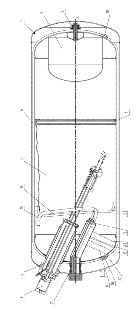
[0038] Such as figure 1 As shown, this kind of liquefied natural gas cylinder for vehicles includes an outer shell 6, an inner tank 5, a cryogenic pump 3 and a liquid level gauge 1. Both the inner tank and the outer shell are provided with front and rear heads. A heat insulating space 12 is formed between them, and the liner 5 is respectively connected to the shell 6 through the front support device 2, the cryopump sleeve device 4 and the rear support device 9, the front support device 2 and the cryopump sleeve device 4 are rigid supports, The rear end supporting device 9 is a soft support.

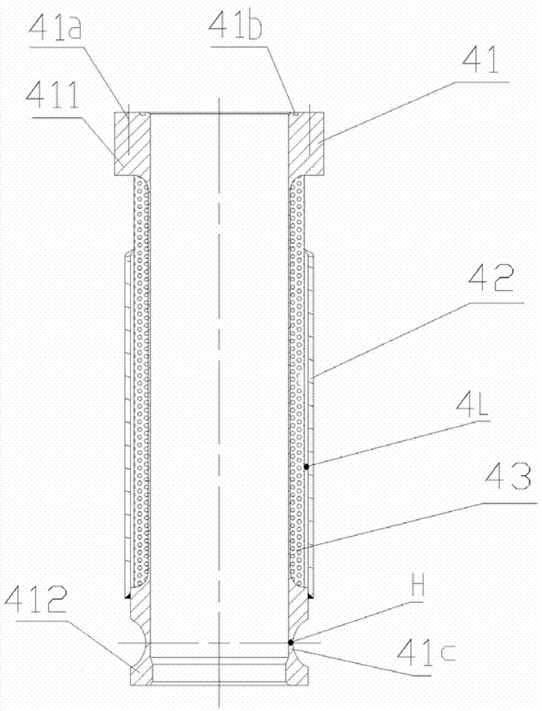
[0039] combine figure 1 and figure 2 As shown, the cryopump sleeve device 4 includes an inner sleeve 41 and an outer sleeve 42, the inner sleeve is arranged in the inner cavity of the outer sleeve, the inner sleeve 41 is an integral structure, and a flange is provided on the u...


PUM

PropertyMeasurementUnit
Angleaaaaaaaaaa
Wall thicknessaaaaaaaaaa

Abstract

The invention relates to an automotive liquefied natural gas cylinder, and provides a liquefied natural gas cylinder integrating a low-temperature pump. Through redesign and reasonable allocation of a support sleeve of the low-temperature pump, the low-temperature pump can be stably arranged, and the heat leakage can be effectively reduced. The automotive liquefied natural gas cylinder comprises a housing, an inner tank and a low-temperature pump, wherein a heat-insulating space is formed between the housing and the inner tank; the inner tank respectively penetrates through a front-end support device, a low-temperature pump sleeve device and a rear-end support device and is connected to the housing; the low-temperature pump sleeve device comprises an inner side sleeve and an outer side sleeve; the inner side sleeve is of an integral structure; a flange plate is arranged on the upper part of the inner side sleeve; a base is arranged on the lower part of the inner side sleeve; a heat-insulating layer is formed between the flange plate and the base on the outer wall of the inner side sleeve; the bottom of the outer side sleeve is welded with the base on the inner side sleeve; and the low-temperature pump is fixedly arranged on the flange plate.

Description

technical field [0001] The invention relates to an improvement of the structure of a gas cylinder, in particular to a liquefied natural gas cylinder for vehicles. Background technique [0002] Natural gas has very good economy, environmental protection and safety. Today, when the world's energy is becoming increasingly tense and air pollution is extremely serious, it will be the future development trend to vigorously promote natural gas clean energy, reduce oil consumption, and reduce pollution emissions in the field of transportation, especially heavy trucks. "New energy industry development" It will be one of China's development priorities during the "Twelfth Five-Year Plan" period. The HC of natural gas heavy trucks has been reduced by 71%, the CO content has been reduced by nearly 90%, the NOX content has been reduced by 35.6%, and the solid particle content has been reduced by almost 100%. [0003] With the adjustment of the national energy structure and the improveme...

Claims


Application Information

Patent Timeline
IPC IPC(8): F17C1/12F17C13/00F17C13/02F17C13/04F17C1/02
Inventor 曹君夏园园杨帆
Owner SHAANXI AUTOMOBILE GROUP
Learn More