Metallurgical Furnace

A metallurgical furnace and furnace cavity technology, applied in the field of metallurgical furnaces, can solve the problems of toxic gas leakage, electrocution, and the inability of the furnace cover to insulate

Active Publication Date: 2015-06-24
JINZHOU TIANSHENG HEAVY IND
View PDF7 Cites 8 Cited by
  • Summary
  • Abstract
  • Description
  • Claims
  • Application Information

AI Technical Summary

Problems solved by technology

[0005] In some furnaces known from the prior art, the roof does not provide sufficient insulation
Furnace lids can be difficult to act as a barrier against toxic gas leaks
Leakage of toxic gases such as carbon monoxide poses a potential hazard to workers
[0006] In some furnaces known from the prior art, the furnace roof may be overheated due to the high temperature generated by the electrodes
Also, the high voltages circulating in the electrodes put workers working near the furnace roof at risk of electrocution

Method used


Image

  • Metallurgical Furnace
  • Metallurgical Furnace
  • Metallurgical Furnace

Examples


Embodiment Construction

[0213] In order to further explain the technical means and effects of the present invention to achieve the intended purpose of the invention, the metallurgical furnace proposed according to the present invention and its specific implementation methods, steps, structures, features and its Efficacy in detail.

[0214] Different embodiments address different aspects of furnace design. It will be appreciated that not all aspects of furnace design discussed herein need be employed to address at least some of the disadvantages involved with existing designs. In some cases, a single aspect described herein may independently address at least some of the known disadvantages. While there are synergies between the various exemplary embodiments, this embodiment would be expected to be used with other conventional furnace designs (e.g., conventional brick refractory and / or electrodes and / or external cooling systems and / or furnace cover design).

[0215] The invention relates to metallur...


PUM

PropertyMeasurementUnit
thicknessaaaaaaaaaa
thicknessaaaaaaaaaa
thicknessaaaaaaaaaa

Abstract

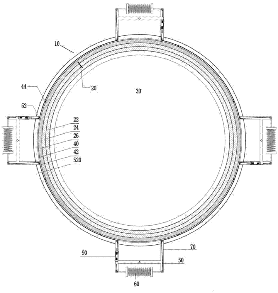
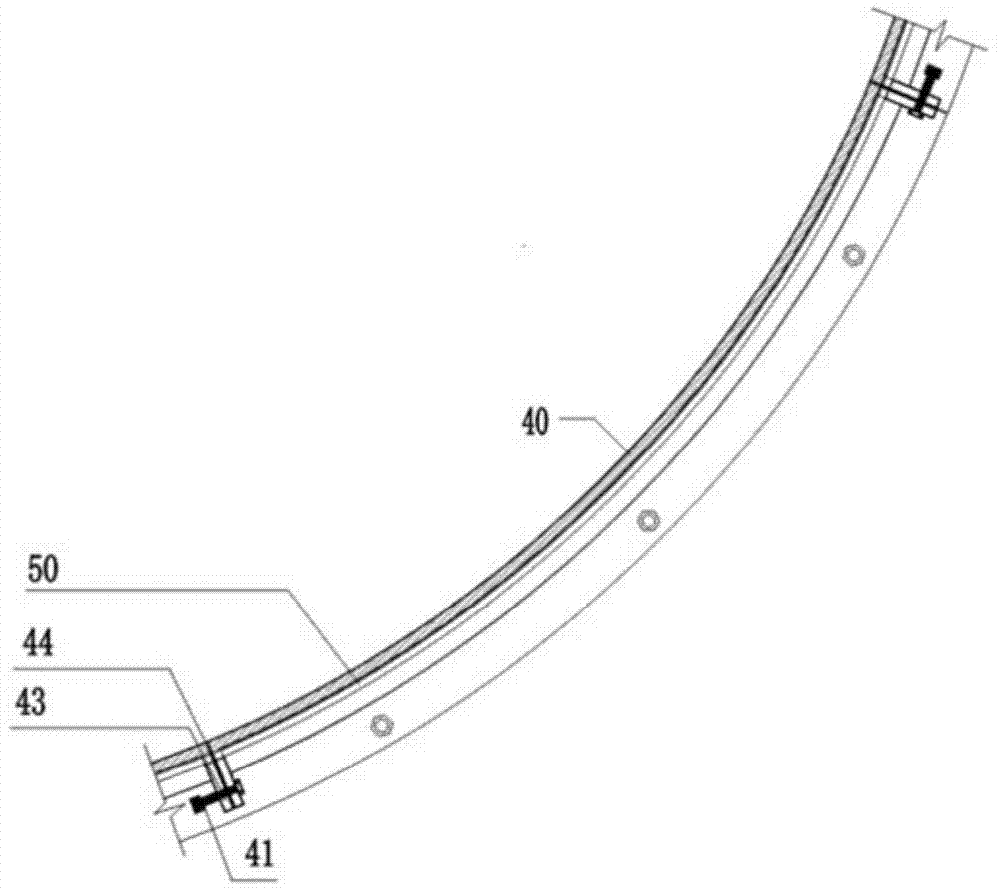
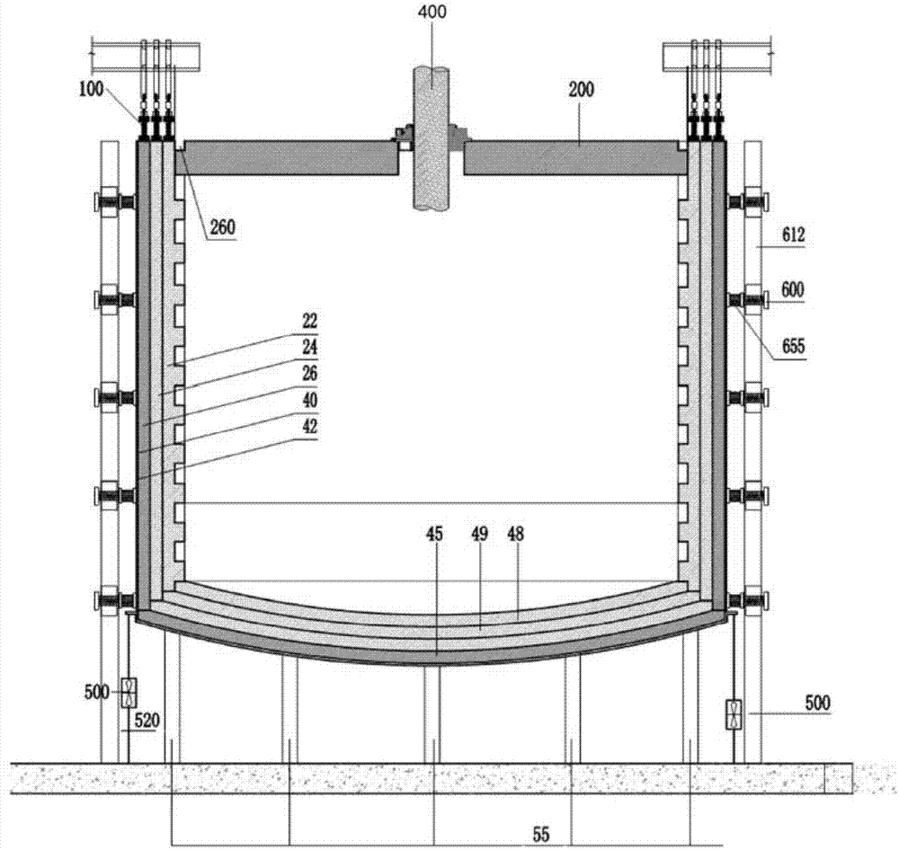
A metallurgical furnace including a refractory, which may include an inner layer, including bricks of a first type having a heat dissipation thickness, and bricks of a second type having a greater sacrificial thickness and protruding towards the furnace space. The furnace may include a force exerting member for contracting a segmented outer shell around the refractory, inward, as the refractory contracts when cooling. The force exerting member may include a tension member. The furnace may include a vertical compression member for exerting a compressive force upon the refractory, vertically compressing the refractory as it contracts. The furnace may include a cooling system, including a sleeve surrounding a layer of heated air, and air displacement members for displacing away the heated air. The furnace may include a roof, having suspension members extending therethrough, supporting an inner mesh, the inner mesh supporting insulating material. The furnace may also include an electrode seal having a plurality of shoes biased against the electrode(s).

Description

technical field [0001] The invention relates to the field of metallurgy, in particular to a metallurgical furnace. Background technique [0002] In the prior art, several forms of metallurgical furnaces are known, consisting of a refractory layer, an outer steel shell surrounding the refractory layer, a furnace cover and a hearth. Metallurgical furnaces known in the prior art may have a rectangular, square or circular cross-section (viewed from directly above or directly below). Metallurgical furnaces known in the prior art generally have a metal structure, supported by a hearth and protected by a refractory layer, in which metal, slag or other substances are heated. Immediately above the heated metal and slag is an area called the "headroom", which is also surrounded laterally by refractory. Metallurgical electric furnaces generally use electricity to heat and melt the contents. It is particularly pointed out that the general circular metallurgical electric furnace uses ...

Claims


Application Information

Patent Timeline
Patent Type & Authority Applications(China)
IPC IPC(8): F27D1/00
CPCF27B3/085F27B3/14F27D1/0023F27D1/08F27D1/14F16J15/028F16J15/067F27B3/10F27D1/045F16J15/43F27B3/20F27D1/0006F27D1/0026F27D1/0043F27D11/10F27D99/0073F27D1/147F27B3/16F27D1/00F27B1/14F27D2099/0021F16J15/002
Inventor 赵桐
Owner JINZHOU TIANSHENG HEAVY IND
Why Eureka
Try Eureka