Parallel breathing type single-plate silo solid carbon fuel cell stack and power generation method thereof

A fuel cell stack and breathing technology, applied in fuel cells, electrochemical generators, circuits, etc., can solve the problems of large circuit consumption in the battery, low battery working efficiency, high reaction temperature, etc., to improve electrode efficiency and fuel efficiency , Reduce the consumption of the circuit in the battery and reduce the cost of use

Active Publication Date: 2018-04-20
ZHANGJIAGANG IND TECH RES INST CO LTD DALIAN INST OF CHEM PHYSICS CHINESE ACADEMY OF SCI
View PDF5 Cites 0 Cited by
  • Summary
  • Abstract
  • Description
  • Claims
  • Application Information

AI Technical Summary

Problems solved by technology

[0025] 1. The working efficiency of the battery is low, the cost is high, the structure is complicated, and the manufacturing is difficult;
[0026] 2. Low power density and high reaction...

Method used


Image

  • Parallel breathing type single-plate silo solid carbon fuel cell stack and power generation method thereof
  • Parallel breathing type single-plate silo solid carbon fuel cell stack and power generation method thereof
  • Parallel breathing type single-plate silo solid carbon fuel cell stack and power generation method thereof

Examples


Embodiment 1

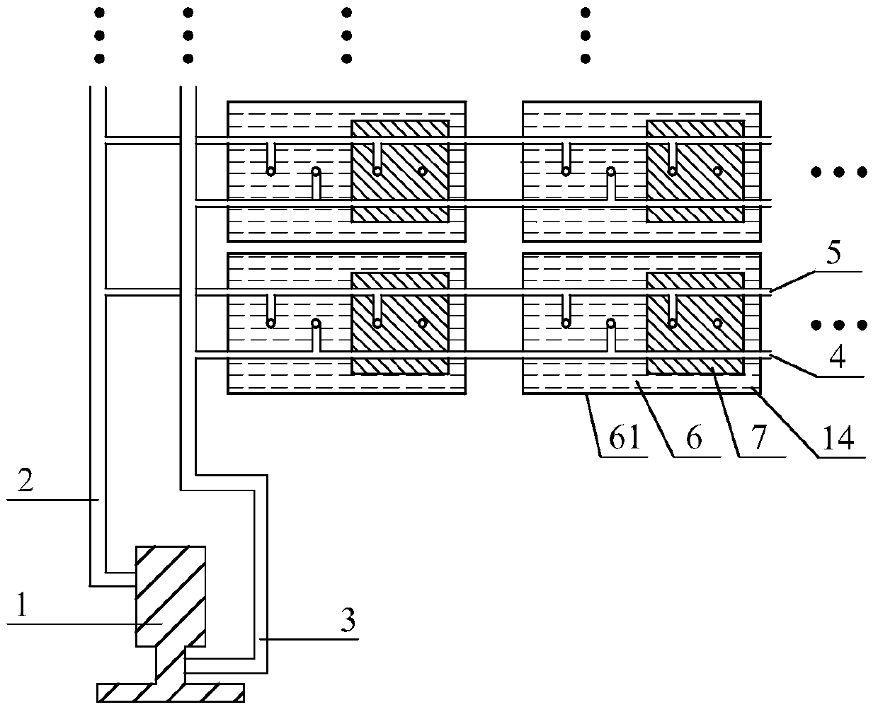
[0074] as attached Figure 1-4 Shown is a solid carbon fuel cell stack in which the parallel breathing single-plate compartment is the cathode plate compartment, including breathing device 1 and battery unit 6. Eighty groups of battery units are connected in parallel to the breathing device, and the high-voltage end of the breathing device is connected to the exhalation device. The main pipeline 2, the low-pressure end of the breathing apparatus is connected to the main suction pipeline 3, the main pipeline is connected to ten branch pipelines 5, the main pipeline is connected to ten branch pipelines 4, and the anode intake pipes of eight battery units 10 and the upper end of the cathode intake pipe 13 are connected to the exhalation branch pipe 5, and the upper ends of the anode exhaust pipe 111 of the eight battery units are connected to the suction branch pipe 4;

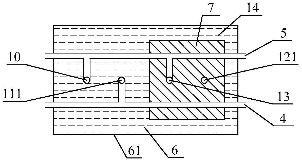
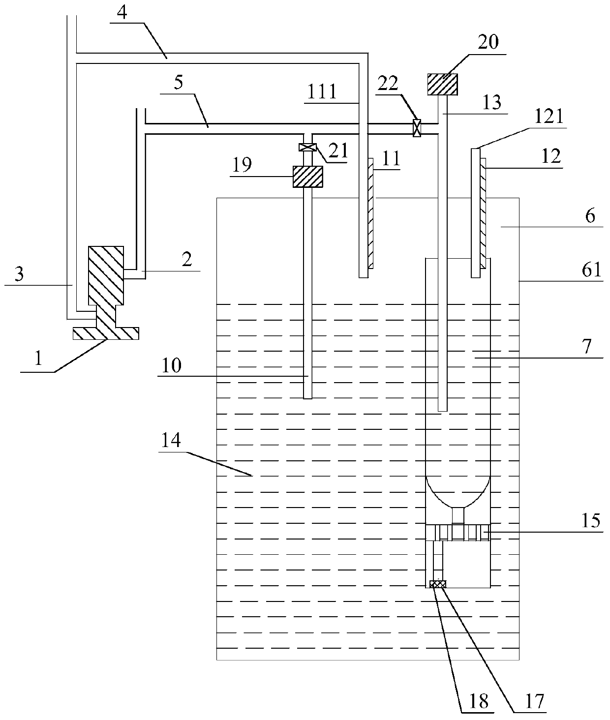
[0075] Each group of battery cells includes an electrolyte bin 61 and a single board bin 7, and the single boa...

Embodiment 2

[0087] This embodiment is identical with embodiment 1 basic structure, and different technical parameters are as follows:

[0088] (1) The single plate warehouse is the anode plate warehouse, and the electrolyte warehouse is the cathode plate warehouse

[0089] (2) A group of battery units are connected in parallel to the breathing apparatus, the high-pressure end of the breathing apparatus is connected to the main exhalation pipe 2, the low-pressure end of the breathing apparatus is connected to the main inhalation pipe 3, and the main exhalation pipe is connected to an exhalation branch pipe 5. The main suction pipe is connected to an suction branch pipe 4, the upper ends of the anode intake pipe 10 and the cathode intake pipe 13 of a group of battery units are connected to the exhalation branch pipe 5, and the anode exhaust pipe of a group of battery units The upper end of 111 is connected to the suction branch pipe 4;

[0090] (3) The breathing device is a turbocharger, a...

Embodiment 3

[0093] This embodiment is identical with embodiment 1 basic structure, and different technical parameters are as follows:

[0094] (1) Six hundred sets of battery units are connected in parallel on the breathing apparatus, the high-pressure end of the breathing apparatus is connected to the main exhalation pipe 2, the low-pressure end of the respiration apparatus is connected to the main inhalation pipe 3, and the main exhalation pipe is connected to ten exhalation branches. Pipeline 5, the suction main pipe is connected to ten suction branch pipes 4, the upper ends of the anode intake pipe 10 and the cathode intake pipe 13 of the sixty battery units are connected to the exhalation branch pipe 5, the anodes of the sixty battery units The upper end of the exhaust pipe 111 is connected to the suction branch pipe 4;

[0095] (2) The breathing device is a piston cylinder, and the breathing frequency of the breathing device is 2Hz.

[0096] (3) The large plate chamber and the smal...


PUM

PropertyMeasurementUnit
Particle sizeaaaaaaaaaa

Abstract

The invention provides a parallel breath-type single-plate cabin solid carbon fuel cell stack and a power generation method thereof, belonging to the technical field of fuel cells. According to the cell stack, a plurality of groups of cell units are connected in parallel; each group of the cell units comprises an electrolyte cabin and a single plate cabin; each single plate cabin is arranged in the corresponding electrolyte cabin; electrolyte is injected into each electrolyte cabin; each single plate cabin is a positive electrode plate cabin and each electrolyte cabin is a negative electrode plate cabin; or each single plate cabin is a negative electrode plate cabin and each electrolyte cabin is a positive electrode plate cabin; positive and negative pressure of positive electrode input gas, negative electrode input gas and positive electrode output gas is provided by a breath device, and the exchanging of electrolyte in the cell is accelerated; the breath device is sufficiently utilized, and a manner of setting the single plate cabin, namely each positive electrode plate cabin or each negative electrode plate cabin is adopted, so that the use cost of the plate cabin is reduced, and furthermore, the electrolyte exchanging is accelerated; the positive electrode plate cabins or the negative electrode plate cabins adopt a spiral pipeline design and a fuel channel is lengthened; meanwhile, the fuel concentration is matched with the surface area of an electrode so that the electrode efficiency and the fuel efficiency are improved; the structure is simple, the manufacturing is easy and the cost is relatively low.

Description

technical field [0001] The invention belongs to the technical field of fuel cells, and in particular relates to a direct solid carbon fuel cell stack, and also relates to its power generation method. Background technique [0002] Energy is the backbone of the human economy and the necessary driving force for social activities. At present, the primary power required for social activities is mainly obtained through heat engines, and then converted into electrical energy. However, since the heat engine is limited by the "Carnot cycle", it is difficult to improve the efficiency, resulting in energy waste and increased pollution emissions. Therefore, the development of efficient and clean electric energy acquisition methods has become an inevitable direction of energy development. [0003] The fuel cell can directly convert the chemical energy stored in the fuel into electrical energy without being limited by the "Carnot cycle". It has the advantages of high energy conversion e...

Claims


Application Information

Patent Timeline
IPC IPC(8): H01M8/0263H01M8/04089H01M8/2465
CPCY02E60/50Y02P70/50
Inventor 岳锌陈芳徐京诚毛莉赵纪军张鹤年
Owner ZHANGJIAGANG IND TECH RES INST CO LTD DALIAN INST OF CHEM PHYSICS CHINESE ACADEMY OF SCI
Why Eureka
Try Eureka