Series-breathing plate-silo-connected solid carbon fuel cell stack and power generation method thereof

A fuel cell stack and fuel cell technology, which is applied in the direction of fuel cell additives, fuel cell grouping, battery pack components, etc., and can solve problems such as manufacturing difficulties, large internal circuit consumption of the battery, and excessive internal resistance

Active Publication Date: 2018-04-20
ZHANGJIAGANG IND TECH RES INST CO LTD DALIAN INST OF CHEM PHYSICS CHINESE ACADEMY OF SCI
View PDF5 Cites 0 Cited by
  • Summary
  • Abstract
  • Description
  • Claims
  • Application Information

AI Technical Summary

Problems solved by technology

[0025] 1. The working efficiency of the battery is low, the cost is high, the structure is complicated, and the manufacturing is difficult;
[0026] 2. Low power density and high reaction temperature;
[0027] 3. The circuit in the battery consumes a lot, the internal resistance is too large, the utilization rate of water is not high, and the service life of the battery is short

Method used


Image

  • Series-breathing plate-silo-connected solid carbon fuel cell stack and power generation method thereof
  • Series-breathing plate-silo-connected solid carbon fuel cell stack and power generation method thereof
  • Series-breathing plate-silo-connected solid carbon fuel cell stack and power generation method thereof

Examples


Embodiment 1

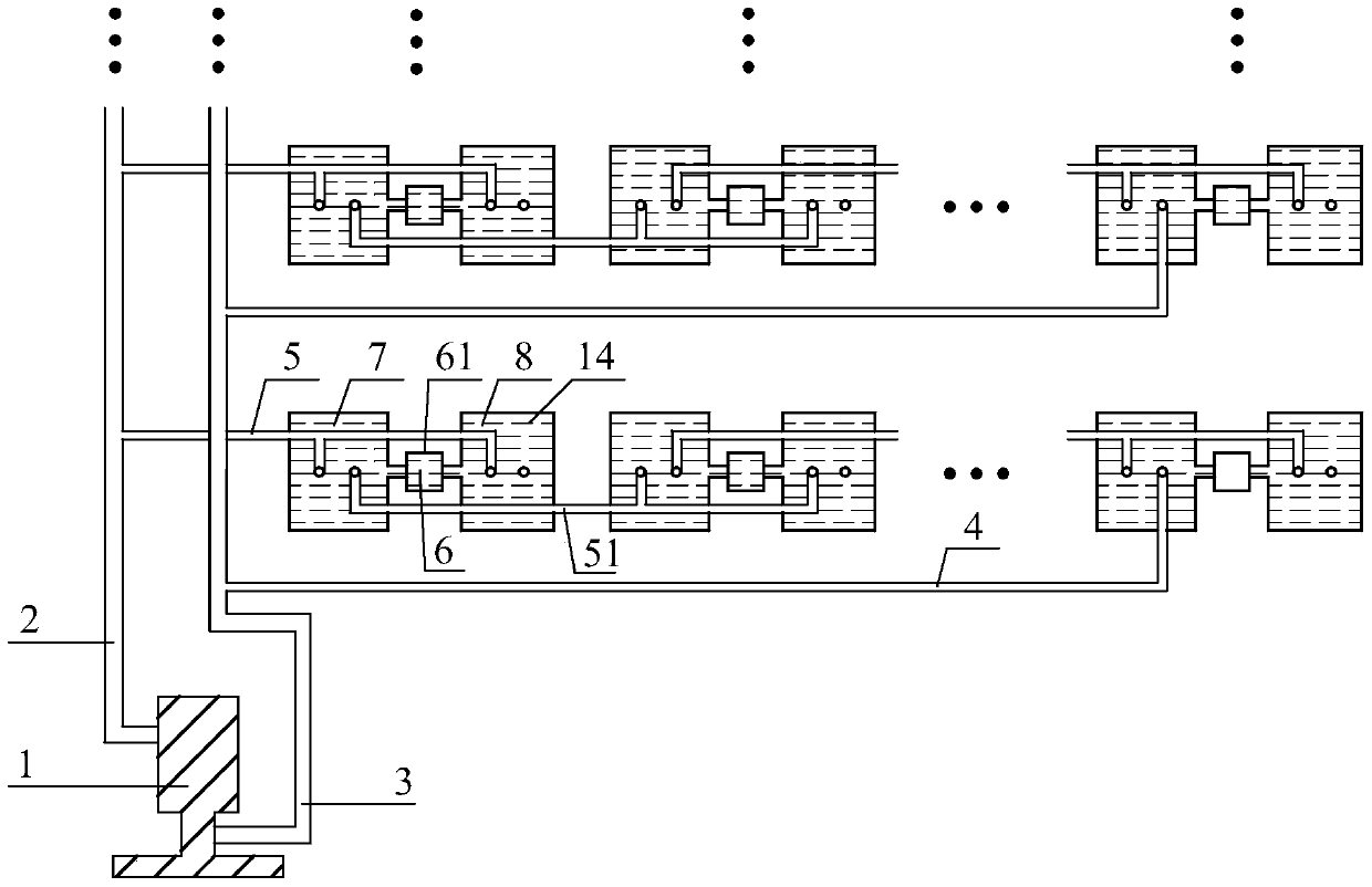
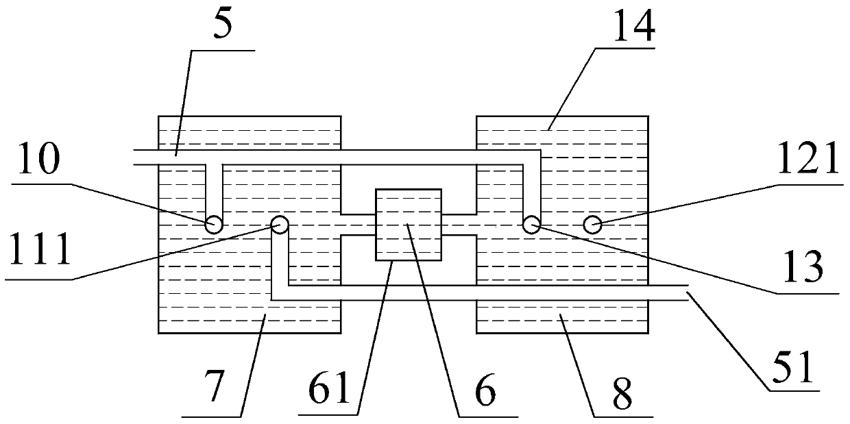
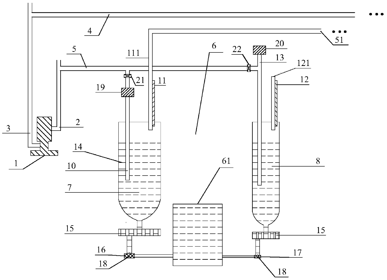
[0080] as attached Figure 1-3 Shown is a solid carbon fuel cell stack connected in series through the electrolyte tank, including a breathing device 1 and a battery unit 6. One hundred series battery packs are connected in parallel to the breathing device, and the high-voltage end of the breathing device is connected to the breathing device. The exhalation main pipeline 2, the low-pressure end of the breathing apparatus is connected to the inhalation main pipeline 3, the exhalation main pipeline is connected to one hundred exhalation branch pipelines 5, and the inhalation main pipeline is connected to one hundred inhalation branch pipelines 4;

[0081] Each group of battery packs connected in series includes sixty groups of battery cells connected in series on the breathing apparatus, wherein the upper ends of the anode air intake pipe 10 and the cathode air intake pipe 13 of the first group of battery cells are all connected on the exhalation branch pipe 5, and the second gro...

Embodiment 2

[0093] This embodiment is identical with embodiment 1 basic structure, and different technical parameters are as follows:

[0094] (1) The connection mode between the anode compartment 7 and the cathode compartment 8 is through an insulating plate with a communication port, and the anode compartment and the cathode compartment are respectively connected through the anolyte communication port 16 and the catholyte communication port 17 Connect to an insulating plate with a communication port, as attached Figure 4 shown.

[0095] (2) Six hundred series battery packs are connected to the breathing apparatus, the high-voltage end of the breathing apparatus is connected to the main exhalation pipe 2, the low-pressure end of the respiration apparatus is connected to the main inhalation pipe 3, and the main exhalation pipe is connected to six hundred exhalation pipes. Branch pipeline 5, the suction main pipeline is connected to six hundred suction branch pipelines 4, and each series...

Embodiment 3

[0099] This embodiment is identical with embodiment 1 basic structure, and different technical parameters are as follows:

[0100](1) The connection between the anode compartment 7 and the cathode compartment 8 is through the electrolyte compartment, and the electrolyte compartment and the connecting pipe are insulated

[0101] (2) A set of battery packs in series is connected to the breathing apparatus, the high-pressure end of the breathing apparatus is connected to the main exhalation pipeline 2, the low-pressure end of the breathing apparatus is connected to the main inhalation pipeline 3, and the main exhalation pipeline is connected to an exhalation branch pipeline 5. The main inhalation pipeline is connected to an inhalation branch pipeline 4, and each series series battery pack includes four hundred sets of battery cells connected in series to the breathing apparatus;

[0102] (3) The breathing device is a piston cylinder, and the breathing frequency of the breathing d...


PUM

PropertyMeasurementUnit
current densityaaaaaaaaaa
particle size (mesh)aaaaaaaaaa

Abstract

The utility model relates to a solid carbon fuel cell stack connected in series breathing type plate bins and a power generation method thereof, belonging to the technical field of fuel cells. The battery stack connects multiple sets of battery cells in series, and then the breathing device provides the positive and negative pressures of the anode intake, cathode intake of the first set of battery cells, and the positive and negative pressure of the anode output of the last set of battery cells to accelerate the electrolyte in the battery. Exchange speed, each group of battery cells includes an anode plate compartment and a cathode plate compartment, the electrolyte flow is carried out by connecting the anode plate compartment and the cathode plate compartment, and the anode plate compartment and the cathode plate compartment are insulated, and the anode plate compartment and the cathode plate compartment are set. The cathode plate compartments are insulated and connected through the electrolyte compartment or an insulating plate with a communication port, which reduces or omits the large-volume electrolyte compartment, reduces costs, and has a higher safety factor. The anode plate compartment or / and cathode plate compartment The spiral pipe design is adopted to extend the fuel channel, and at the same time, the fuel concentration matches the electrode surface area, which improves the electrode efficiency and fuel efficiency, and the cost is low.

Description

technical field [0001] The invention belongs to the technical field of fuel cells, and in particular relates to a breathing type solid carbon fuel cell stack, and also relates to a power generation method thereof. Background technique [0002] Energy is the backbone of the human economy and the necessary driving force for social activities. At present, the primary power required for social activities is mainly obtained through heat engines, and then converted into electrical energy. However, since the heat engine is limited by the "Carnot cycle", it is difficult to improve the efficiency, resulting in energy waste and increased pollution emissions. Therefore, the development of efficient and clean electric energy acquisition methods has become an inevitable direction of energy development. [0003] The fuel cell can directly convert the chemical energy stored in the fuel into electrical energy without being limited by the "Carnot cycle". It has the advantages of high energ...

Claims


Application Information

Patent Timeline
Patent Type & Authority Patents(China)
IPC IPC(8): H01M8/24H01M8/04H01M2/20
CPCY02P70/50Y02E60/50
Inventor 岳锌陈芳徐京诚毛莉赵纪军张鹤年
Owner ZHANGJIAGANG IND TECH RES INST CO LTD DALIAN INST OF CHEM PHYSICS CHINESE ACADEMY OF SCI
Why Eureka
Try Eureka