Device and method for welding high steel grade and large wall thickness pipeline steel

A pipeline steel, steel grade technology, applied in welding equipment, welding accessories, arc welding equipment and other directions, can solve the problem of not clearly specifying the ultrasonic device or workpiece and welding torch, limiting the wide application of ultrasonic-assisted welding, and high requirements for feeding systems. Achieve the effect of improving the quality of welded joints, improving mechanical properties, and improving the degree of homogenization

Inactive Publication Date: 2015-07-08
SOUTHWEST PETROLEUM UNIV
View PDF9 Cites 15 Cited by
  • Summary
  • Abstract
  • Description
  • Claims
  • Application Information

AI Technical Summary

Problems solved by technology

[0003] In the existing technology, the patent 200810064099.6 is a welding method and its device combining ultrasonic vibration and welding wire feeding system. It adopts ultrasonic wave on the wire feeding nozzle that is smoothly connected with the welding wire, and the vibration of the wire feeding nozzle drives the welding wire Vibration, this will inevitably cause waste of ultrasonic energy, and it will be a test for the life of the wire feeder under large vibrations. In addition, the welding torch needs to move during the welding process of the workpiece, so the ultrasonic device added to the wire feeder needs to be moved at the same time. The invention does not clearly explain how the ultrasonic device or the workpiece and welding torch achieve moving welding
In addition, this set of devices has high requirements on the feeding system of welding wire. Generally, it is very difficult to add ultrasonic waves to the wire feeding nozzle for non-independent wire feeding devices.
It is suitable for non-melting electrode arc welding, but it cannot be applied to melting electrode arc welding such as carbon dioxide gas shielded welding. The above characteristics limit the wide application of ultrasonic assisted welding

Method used


Image

  • Device and method for welding high steel grade and large wall thickness pipeline steel
  • Device and method for welding high steel grade and large wall thickness pipeline steel
  • Device and method for welding high steel grade and large wall thickness pipeline steel

Examples


Embodiment 1

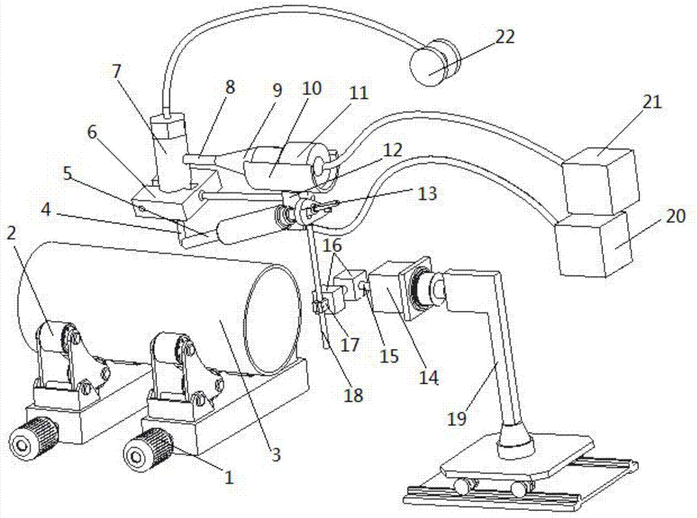
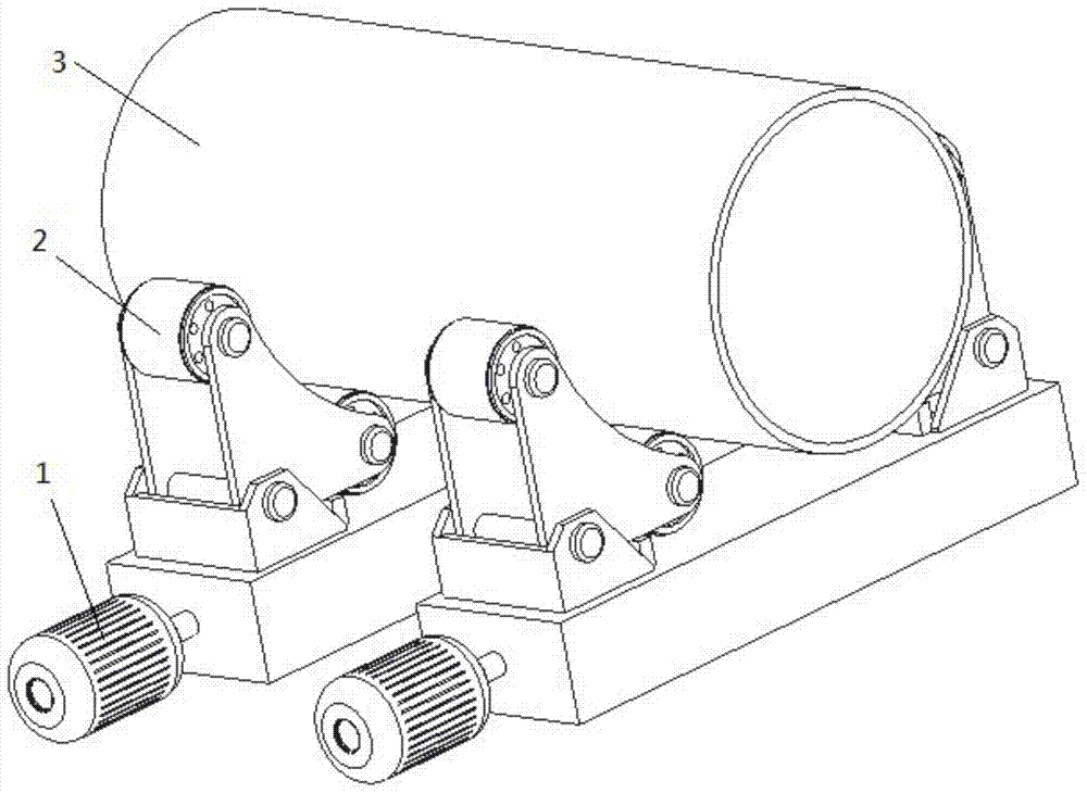
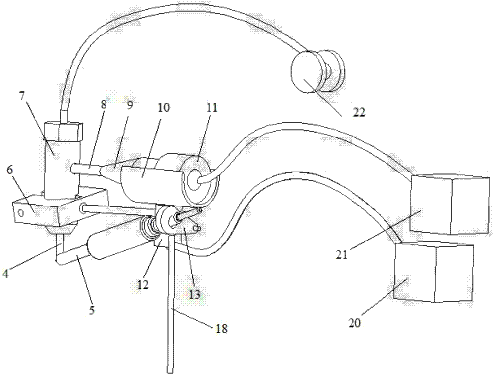
[0040] combine figure 1 , the method for welding high steel grade and large wall thickness pipeline steel using the above-mentioned device, the steps are as follows: first start the workbench controller 1 to make the workpiece 3 rotate at a constant speed according to the set speed, then turn on the welding power supply 20, and wait for the arc After stabilization, start the ultrasonic generator 21 again, so that the ultrasonic transducer 11 converts electrical energy into ultrasonic vibration, and the amplitude of the ultrasonic vibration is amplified by the horn 9 and the ultrasonic tool head 8 and then directly transmitted to the welding wire 4 . The angle of the welding torch 5 is adjusted by the angle regulator 16 so that it is aligned with the weld seam, and finally the swinger 14 and the wire feeding mechanism 22 are started, the welding wire 4 is sent out smoothly by the wire feeding mechanism 22, and the drive shaft 15 is driven in and out by the swinger 14 , thereby ...


PUM


Abstract

The invention discloses a device and a method for welding high steel grade and large wall thickness pipeline steel. The device for welding the high steel grade and large wall thickness pipeline steel is mainly composed of a work platform controller 1, an idler wheel support 2, a work piece 3, a welding gun 5, a wire feeding nozzle 7, an ultrasonic tool head 8, an amplitude variation pole 9, an ultrasonic transducer 11, a welding power source 20, an ultrasonic generator 21, a wire feeding mechanism 22, an oscillator 14, a transmission shaft 15, an angle adjustor 16 and the like. The method for welding the high steel grade and large wall thickness pipeline steel includes: (1) placing the work piece on the idler wheel support, and starting the work platform controller; (2) setting welding voltage and a welding current, turning on the welding power source, and starting the ultrasonic generator after an electric arc is stabilized; (3) adjusting angles of the welding gun through the angle adjustor; (4) starting the oscillator, and driving the welding gun to swing back and forth through entrance and exiting movements of the transmission shaft; (5) starting the wire feeding mechanism, and staring automatic welding. The device and the method for welding the high steel grade and large wall thickness pipeline steel achieve high welding quality, good weld joint formation, and a high welding joint microstructure constituent homogenization degree, and have a broad market application prospect.

Description

technical field [0001] The invention relates to a welding device and method for high steel grade and large wall thickness pipeline steel, which is to directly add ultrasonic vibration to the welding wire to make the welding wire vibrate. The welding device and method can be applied to high steel grade and large wall thickness. Thick pipeline steel non-melting pole or melting pole gas shielded welding. Background technique [0002] For high-grade steel, two problems often occur in the welding of pipeline steel with large wall thickness. First, when the heat input is too small, the weld will appear a brittle-hard second phase structure, and the strength and hardness will increase, but the toughness will be greatly reduced. There may be quality problems such as incomplete penetration, insufficient weld pool depth, and poor post-weld forming. Secondly, after the heat input is too large, the grains in the overheated zone of the heat-affected zone will grow excessively, which will...

Claims


Application Information

Patent Timeline
Patent Type & Authority Applications(China)
IPC IPC(8): B23K9/16B23K9/32
Inventor 王斌田晓宇吴立斌武斌王良
Owner SOUTHWEST PETROLEUM UNIV
Why Eureka
Try Eureka