Single-pulse laser dynamic focal spot position measuring device and method

A measuring device and single-pulse technology, applied in the field of optics, can solve problems such as small measurement range and low stability

Inactive Publication Date: 2015-07-08
XI'AN INST OF OPTICS & FINE MECHANICS - CHINESE ACAD OF SCI
View PDF7 Cites 8 Cited by
  • Summary
  • Abstract
  • Description
  • Claims
  • Application Information

AI Technical Summary

Problems solved by technology

[0004] In order to solve the technical problems of small measurement range and low stability in the existing method for measuring the foc...

Method used


Image

  • Single-pulse laser dynamic focal spot position measuring device and method
  • Single-pulse laser dynamic focal spot position measuring device and method
  • Single-pulse laser dynamic focal spot position measuring device and method

Examples


Embodiment Construction

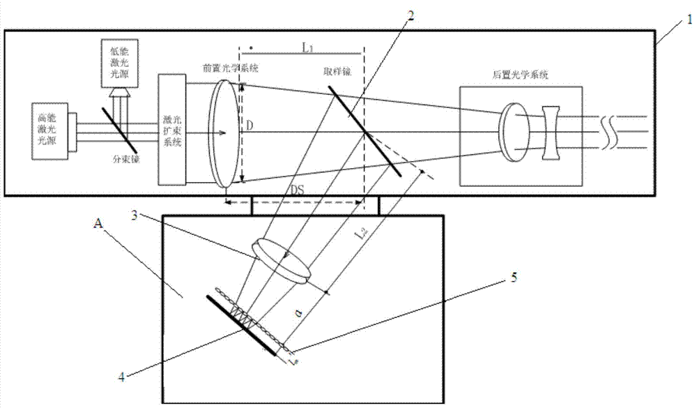
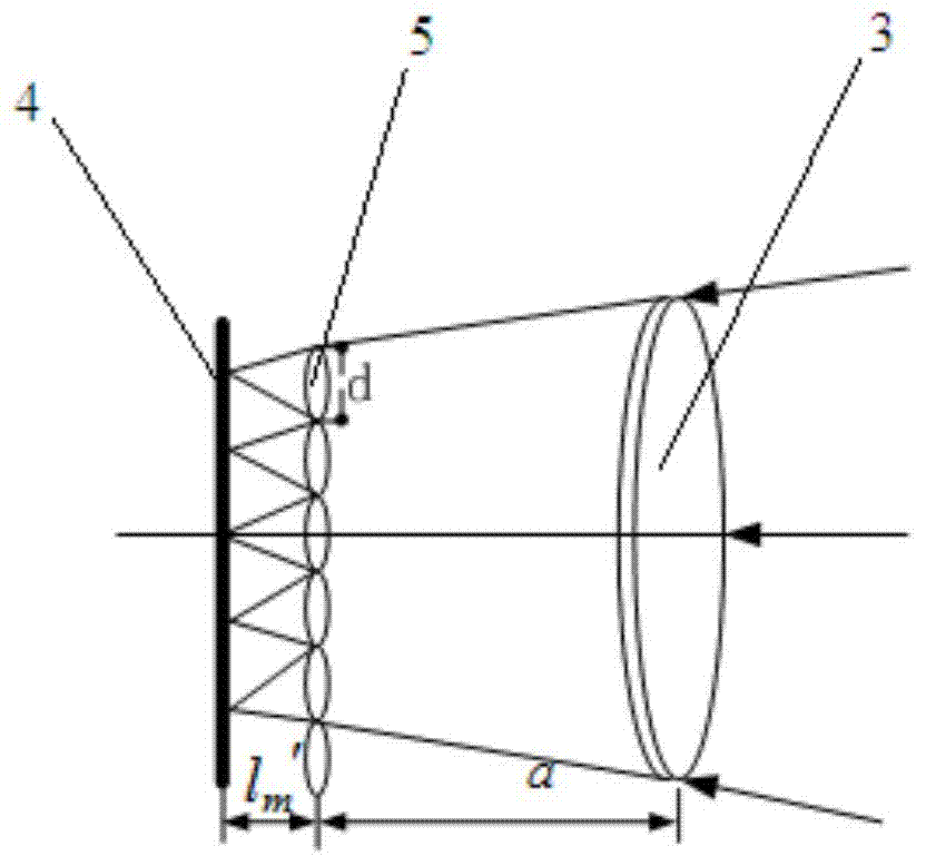
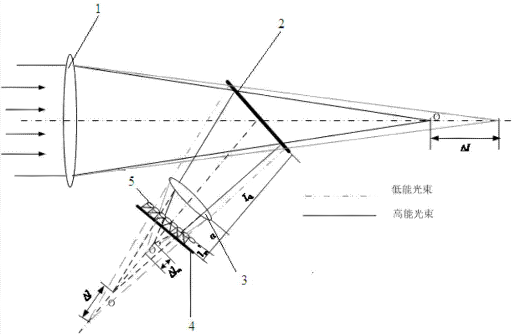
[0059] Such as figure 1 , figure 2 As shown, the laser dynamic focal spot position measurement device includes five parts: an optical system to be tested 1, a sampling mirror 2, a standard converging lens 3, a microlens array 5, a CCD detector 4 and a mechanical casing. The sampling mirror samples the beam to be measured, the converging lens converges the sampled beam, and the converged beam is sent to the microlens array, and the beam is imaged on the CCD detector after being converged by the microlens array. The mechanical casing covers and packages all the devices together, and the mechanical parts ensure the structural parameters of the system while preventing external stray light from affecting the measurement. In the low-energy state, the focus position of the system under test is o. The standard converging lens takes the focus of the system under test as the object for primary imaging, and the microlens array takes the image point of the converging lens as the object ...


PUM


Abstract

The invention relates to a single-pulse laser dynamic focal spot position measuring device and method. The device comprises an optical system to be measured, a sampling mirror, a standard convergence lens, a microlens array, a CCD detector and a shell. The optical system to be measured provides a light beam to be measured. The sampling mirror samples the light beam to be measured and obtains a sampled light beam. The standard convergence lens carries out convergence processing on the sampled light beam to obtain a convergent light beam and transmits the convergent light beam to the microlens array. The microlens array is used for enabling the convergent light beam to converge again and imaging the convergent light beam on the CCD detector. The sampling mirror, the standard convergence lens, the microlens array and the CCD detector are sequentially packaged in the shell in the light path transmission direction. The technical problem that an existing focal spot measuring method is small in measuring range and not high in stability is solved, and the measuring precision and range of the whole system are high in adjustability.

Description

technical field [0001] The invention belongs to the field of optics, and relates to a dynamic focal spot position measurement device for a high-energy laser system, which can complete the dynamic focal spot position detection of a long focal length, high energy, and single-pulse laser system, and a single measurement can realize the focus along the axis and the vertical axis Spot drift detection. Background technique [0002] With the maturity of laser technology, more and more large-scale, complex and high-energy laser systems have emerged in the field of optics. The focal spot position of a high-energy laser system is an important parameter for evaluating the beam quality of the system, and the variation of the focal spot position of the laser beam is an important reference for system installation and debugging. In practical applications, due to thermal distortion in the strong laser system (refractive index changes caused by thermal stress, glass shape distortion caused ...

Claims


Application Information

Patent Timeline
IPC IPC(8): G01M11/00
Inventor 董晓娜赵娟宁袁索超
Owner XI'AN INST OF OPTICS & FINE MECHANICS - CHINESE ACAD OF SCI
Why Eureka
Try Eureka