Detecting device and detecting method for surface evenness of gate

A surface smoothness and detection device technology, applied in the field of measurement, can solve the problems of unsuitable detection of gate water level fluctuation areas, different ultrasonic propagation speeds, and influence on detection results, etc., to achieve high adaptability, high degree of mechanical automation, and data observation convenient effect

Active Publication Date: 2015-07-15
HOHAI UNIV
8 Cites 21 Cited by

AI-Extracted Technical Summary

Problems solved by technology

At present, the invention has announced a device for detecting the deformation of the gate, including electromagnets, steel strings, probes, steel plates, wires, system power supplies, information conditioning circuits, single-chip microcomputers, data collectors and power amplifiers. The invention mainly uses eddy current detection technology, through Measure the distance between the probe and the steel plate to detect whether the surface of the gate is deformed, but becaus...

Abstract

The invention relates to a detecting device and a detecting method for surface evenness of a gate. The detecting device comprises two longitudinal slideways symmetrically arranged on two sides of the upstream surface of the gate, the two longitudinal slideways are both internally provided with movable plates, a horizontal rail is arranged between the movable plates, the horizontal rail is provided with an elastic pressure-sensitive box, the elastic pressure-sensitive box is internally provided with a steel ball which abuts against the gate, a spring is squeezed by the steel ball, the spring is connected with a pressure sensor., and the pressure sensor is connected with a data meter through a data line. The detecting method for the surface evenness of the gate comprises the following steps that 1 the detecting device for the surface evenness of the gate is installed; 2 a coordinate system is established; 3 the surface of the gate is detected; 4 data processing is conducted. The adaptability for environment is high, the mechanical automation degree is high, locating is accurate, the cost is low, and the device and method are easy to achieve.

Application Domain

Technology Topic

Image

  • Detecting device and detecting method for surface evenness of gate
  • Detecting device and detecting method for surface evenness of gate
  • Detecting device and detecting method for surface evenness of gate

Examples

  • Experimental program(1)

Example Embodiment

[0031] The present invention will be further explained below in conjunction with the accompanying drawings and specific embodiments. It should be understood that the following specific embodiments are only used to illustrate the present invention and not to limit the scope of the present invention.
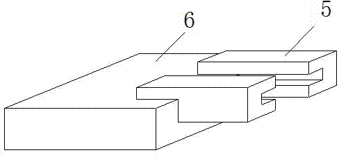
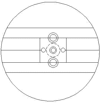
[0032] figure 1 is a schematic diagram of the overall structure of the present invention, Figure 4 Yes figure 1 In the partial enlarged view of C in the figure, it can be seen from the figure that the detection device for the surface flatness of the gate 8 is installed on the upstream surface of the gate 8. The detection device includes a horizontal rail 9, an elastic pressure-sensitive box 10, a data meter 1 and Two longitudinal slides 7, the data meter 1 is arranged vertically above the gate 8, the two longitudinal slides 7 are symmetrically arranged on both sides of the upstream surface of the gate 8, and both longitudinal slides 7 are provided There is a moving plate 6 that can slide up and down in the corresponding longitudinal slideway 7. Both ends of the horizontal rail 9 are respectively fixed with the moving plate 6. The horizontal rail 9 can follow the moving plate 6 to move up and down on the surface of the gate 8. The elastic pressure-sensitive cartridge 10 is slidably arranged in the horizontal rail 9 .
[0033] The horizontal ends of the elastic pressure-sensitive box 10 are connected with the data instrument 1 through the measuring rope 2, and the elastic pressure-sensitive box 10 can be moved horizontally in the horizontal rail 9 by pulling the measuring rope 2. The two moving plates 6 are lifted and lowered respectively. The rope 3 is connected with the data instrument 1 , and the moving plate 6 can be moved up and down in the longitudinal slideway 7 by pulling the lifting rope 3 . The elastic pressure-sensitive box 10 can move horizontally. Combined with the elastic pressure-sensitive box 10 moving up and down together with the moving plate 6 , the elastic pressure-sensitive box 10 can detect any position on the surface of the gate 8 .
[0034] The tops of the two longitudinal slideways 7 and the surfaces of the two moving plates 6 are provided with direction changing wheels, and the measuring rope 2 changes direction twice through the direction changing wheels corresponding to the tops of the longitudinal slideways 7 and the surfaces of the moving plates 6, Finally connected to the elastic pressure-sensitive box 10 , the lifting rope 3 is connected to the moving plate 6 after changing the direction of the direction changing wheel corresponding to the top of the longitudinal slide 7 . The measuring rope 2 and the lifting rope 3 change directions for corresponding times respectively to ensure that the measuring rope 2 and the lifting rope 3 will not rub against or touch other objects.
[0035] The longitudinal slideway 7 is provided with a chute, and the sliding plate is provided with an "I"-shaped slider stuck in the chute, and the moving plate 6 moves up and down in the longitudinal slideway 7 by sliding the slider in the chute. ; The longitudinal slideway 7 is laid with electromagnets, the moving plate 6 is selected from metal materials containing iron, cobalt and nickel, and the moving plate 6 can be adsorbed in the longitudinal slideway 7 by the electromagnet. Combined with the chute and the electromagnet, it can ensure that the moving plate 6 moves up and down in the longitudinal slide 7 and will not fall out.
[0036] figure 2 It is a schematic structural diagram of the elastic pressure-sensitive box 10 of the present invention. As can be seen from the figure, the elastic pressure-sensitive box 10 is provided with a steel ball 11, a pressure sensor 16 and a spring 12 on the side facing the gate 8, and one end of the spring 12 squeezes the steel ball 11. The other end is pressed against the shutter 8, and the other end is fixedly pressed against the pressure sensor 16 in the elastic pressure-sensitive box 10, and the pressure sensor 16 is connected to the data instrument 1 through a data cable. The elastic pressure sensitive box 10 is also provided with a threaded column 15, a steel plate 14 and an I-shaped nut 17, the steel plate 14 is clamped in the I-shaped nut 17, and the pulleys 18 on the upper and lower edges of the steel plate are clamped into the horizontal rail. The I-shaped nut 17 is tightly connected with the threaded column 15, and the threaded column 15 is fixed on the side of the elastic pressure-sensitive box 10 away from the gate. The steel plate 14 is provided with two through holes 13 in the horizontal direction. A measuring cord passes through the corresponding through holes 13 respectively and is fixed with the steel plate 14 .
[0037] image 3 It is a diagram of the connection position between the moving plate 6 of the present invention and the horizontal rail 9. As can be seen from the figure, the horizontal rail 9 includes two rail slats 5, and the opposite side of the rail slats 5 is provided with a "concave" shaped horizontal rail 9 The pulleys 18 on the upper and lower edges of the steel plate 14 are stuck in the grooves of the horizontal rail 9 , and the through holes 13 on the steel plate 14 are located in the middle of the two rail slats 5 .
[0038] The data meter 1 is provided with a data collector, a control system and a display screen, the data collector is connected with the pressure sensor 16 through a data line, and the display screen displays the data collected and processed by the data collector; the data meter 1 is also provided with a reel A and a reel B, the two measuring ropes 2 and the two lifting ropes 3 are respectively wound on the reel A according to the same direction, the measuring rope 2 is also wound on the reel B, and the two measuring ropes are wound on the reel A in the same direction. 2. The winding direction on the reel B is opposite, the control system controls the rotation of the reel A and the reel B, and the control system can calculate the position of the elastic pressure-sensitive box 10 on the surface of the gate 8 according to the rotation situation, and the position can be determined by Cartesian coordinates. The system is displayed on the display.
[0039] A method for detecting the surface flatness of a gate, which uses a device for detecting the surface flatness of a gate, comprising the following operation steps:
[0040] (1) Install the detection device for the surface flatness of the gate: two longitudinal slideways are symmetrically arranged on both sides of the upstream surface of the gate, a moving plate is symmetrically arranged in the two longitudinal slideways, a horizontal track is arranged in the middle of the moving plate, and elastic is installed in the horizontal track The pressure-sensitive box, the moving plate and the elastic pressure-sensitive box are respectively connected with the reel in the data meter above the gate through the lifting rope and the measuring rope, and the pressure sensor in the elastic pressure-sensitive box is connected with the data collector in the data meter through the data cable. connect;
[0041] (2) Establish coordinate system: establish a plane rectangular coordinate system on the display screen, select any point as the origin of the plane rectangular coordinate system, and any position on the gate surface can be represented by the plane rectangular coordinate system;
[0042] (3) Detecting the gate surface: by rotating the reel A, the moving plate can move up and down in the longitudinal slideway, and the measuring rope is also kept in a tensioned state, so that the elastic pressure-sensitive box can detect any height of the gate, and the elastic pressure-sensitive can be realized by rotating the reel B. The box can move horizontally on the horizontal track, so that the elastic pressure-sensitive box can detect any horizontal position of the gate, and finally can detect any position on the surface of the gate;
[0043] (4) Data processing: one side of the steel ball in the elastic pressure-sensitive box is pressed against the gate, and the other side is against the spring. When it is flat, the voltage signal output by the data meter is stable, and when the surface of the gate is concave or convex, the voltage signal output by the data meter fluctuates accordingly. on the display.
[0044] In the step (3), any coordinate value is input to the control system through the display screen, and the control system can control the rotation of the reel A and the reel B to move the elastic pressure-sensitive box to the position corresponding to the coordinate value.
[0045] The technical means disclosed in the solution of the present invention are not limited to the technical means disclosed by the above-mentioned technical means, but also include technical solutions composed of any combination of the above-mentioned technical features.

PUM

no PUM

Description & Claims & Application Information

We can also present the details of the Description, Claims and Application information to help users get a comprehensive understanding of the technical details of the patent, such as background art, summary of invention, brief description of drawings, description of embodiments, and other original content. On the other hand, users can also determine the specific scope of protection of the technology through the list of claims; as well as understand the changes in the life cycle of the technology with the presentation of the patent timeline. Login to view more.

Similar technology patents

Anti-failure pneumatic window opener

ActiveCN109914958ASimple working principleThe structure is easy to disassemblePower-operated mechanismWing openersPistonAir spring
Owner:郑州洪华建筑科技有限公司

Classification and recommendation of technical efficacy words

  • Simple working principle
  • Improve adaptability

Safety rod driving system of liquid heavy metal cooling reactor

Owner:HEFEI INSTITUTES OF PHYSICAL SCIENCE - CHINESE ACAD OF SCI
Why Eureka
Try Eureka