Multi-section plasma cracking carbonaceous material reactor system

A reactor system, plasma technology, used in hydrocarbon oil cracking, cracking, educts, etc.

Active Publication Date: 2015-07-22
CHNA ENERGY INVESTMENT CORP LTD +1
View PDF7 Cites 12 Cited by
  • Summary
  • Abstract
  • Description
  • Claims
  • Application Information

AI Technical Summary

Problems solved by technology

In the above-mentioned multi-section plasma cracking carbonaceous material reactor system, since a chamber for generating plasma and / or electric arc is formed between each section of the hollow cathode and the hollow anode, it is located in the reaction tube of each section, and the carbonaceous material and / or Or the pyrolysis volatile matter and the plasma gas flow are also fully contacted and mixed at or near the highest temperature region of the above-mentioned chamber in each section of the reaction tube, so that although the thermal efficiency of the reactor is greatly improved, each section of the reaction tube When the temperature of the medium carbonaceous material or pyrolysis product is too high, and the reaction tube wall is not properly protected, this reactor structure and feeding arrangement lead to almost unavoidable coking, because the high temperature carbonaceous material powder or gaseous pyrolysis The product has the potential to continuously contact or wash off the wall surface of the reactor
[0009] In the above-mentioned existing plasma reactor, no matter how the reactor structure is designed, improving thermal efficiency and cracking product yield and eliminating coking on the wall surface of the reactor have almost become an irreconcilable contradiction. How to simultaneously improve thermal efficiency and cracking product yield And eliminating coking on the surface of the reactor wall is a problem that plagues the industry

Method used


Image

  • Multi-section plasma cracking carbonaceous material reactor system
  • Multi-section plasma cracking carbonaceous material reactor system
  • Multi-section plasma cracking carbonaceous material reactor system

Examples


Embodiment 1

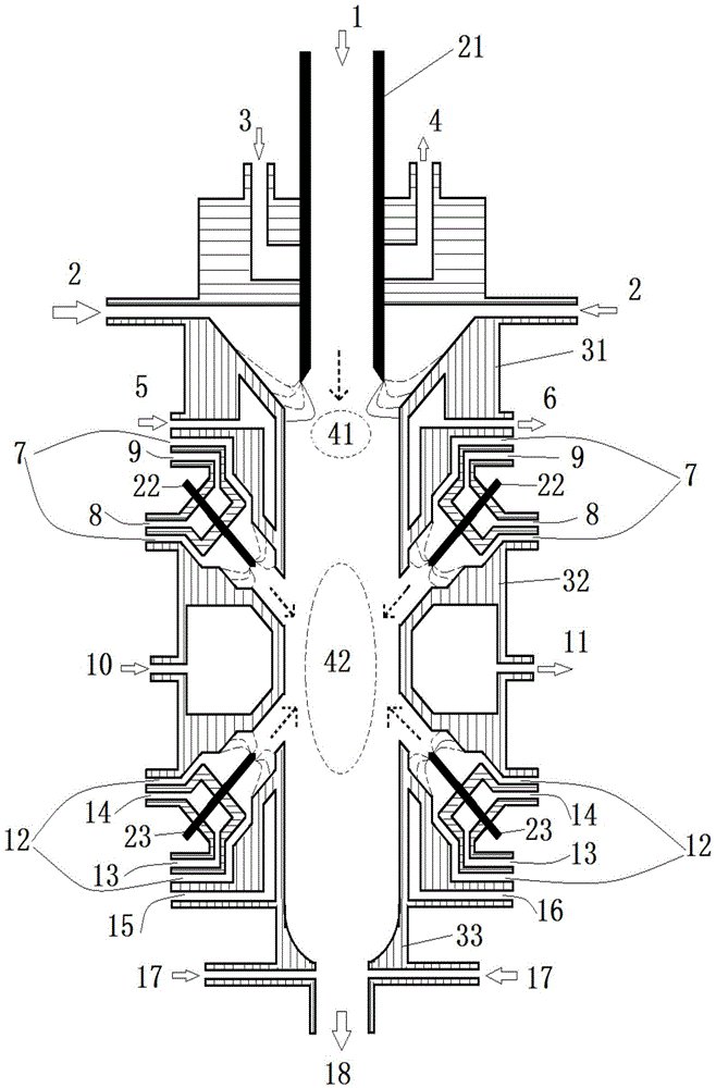
[0075] Schematic for figure 1 The reactor system of the present invention for multi-stage plasma cracking of carbonaceous materials is used to convert coal tar to acetylene and other chemicals. A coal tar produced during coal pyrolysis was used as a carbonaceous material, and its properties are shown in Table 1.

[0076] Table 1

[0077]

[0078] In the above-mentioned multi-stage plasma reactor system of the present invention, the input power of the hollow cathode 21 of the preheating section and its plasma torch is 5kW, and the input power of the four cathode rods 22 and 23 of the mixed reaction section and its plasma torch are both It is 5kW, in order to form one arc area for generating plasma in the preheating section and four arc areas for generating plasma in the mixing reaction section.

[0079] like figure 1As shown, the 300K coal tar feed 1 is introduced into the reaction tube of the preheating section through the hollow channel of the hollow cathode 21 under th...


PUM

PropertyMeasurementUnit
particle sizeaaaaaaaaaa
thermal decomposition temperatureaaaaaaaaaa
thicknessaaaaaaaaaa

Abstract

The invention discloses a multi-section plasma cracking carbonaceous material reactor system which includes a preheating section, at least one hybrid reaction section, at least one chilling medium inlet and at least one chilling product outlet, wherein the preheating section includes a hollow cathode and an anode; carbonaceous material enters a reaction tube of the preheating section through a hollow passage of the hollow cathode; the at least one hybrid reaction section includes a plurality of cathode bars and anodes corresponding to the cathode bars; a plasma and or / arc forming region formed between the hollow cathode and the anode is positioned inside the reaction tube, and a plasma and or / arc forming region formed among the cathode bars and the anodes is positioned outside the reaction tube; a plurality of streams of plasma gas collides at the center of or near to the reaction tube of the preheating section, and is in convection contact with and intensely mixed with carbonaceous material and carrier gas, so that preheated carbonaceous material is heated, carbonaceous material is subjected to pyrolysis and cracking, and then carbonaceous material subjected to pyrolysis and cracking is subjected to volatile matter gas-phase reaction. The reactor system provided by the invention is excellent in carbon deposition prevention and thermal efficiency and higher in split product productivity.

Description

technical field [0001] The present invention relates to a high-energy-efficiency device and method for cracking carbonaceous materials containing volatile components to produce high-yield cracked products, in particular, to a multi-stage plasma cracking carbonaceous material reactor system and utilizing the multi-stage plasma A method of cracking carbonaceous materials by a reactor system, and more particularly, relates to a method of producing acetylene using the multi-stage plasma reactor system. Background technique [0002] The composition of products resulting from cracking or pyrolysis of carbonaceous materials depends on the reaction conditions. It is well known that some specific reaction conditions are favorable for the formation of some specific components, for example, the formation of intermediate product acetylene is favorable when the temperature of the reaction zone is higher than 1300K. [0003] Generally speaking, when an arc is used as a heat source, the a...

Claims


Application Information

Patent Timeline
Patent Type & Authority Applications(China)
IPC IPC(8): B01J19/08C10B53/04C10B53/07C10B53/00C10G15/12C07C11/24C07C11/04C07C9/04C07C1/00C07C1/20
CPCB01J19/08C07C1/00C07C4/04C10B53/00C10B53/04C10B53/07C10G15/12C07C11/24C07C11/04C07C9/04Y02P20/143Y02P30/20Y02P30/40
Inventor 李轩苗强韩建涛黄峰
Owner CHNA ENERGY INVESTMENT CORP LTD
Why Eureka
Try Eureka