A skid-mounted automatic liquid discharge device for venting and separating liquid

An automatic liquid drainage and skid-mounted technology, which is applied in the direction of gas/liquid distribution and storage, pipeline systems, mechanical equipment, etc., can solve problems such as heavy workload, increased workload, pipeline slug flow, etc., and improve work efficiency , Reduce labor intensity and prevent slug flow

Active Publication Date: 2017-09-26
XIAN CHANGQING TECH ENG
View PDF6 Cites 0 Cited by
  • Summary
  • Abstract
  • Description
  • Claims
  • Application Information

AI Technical Summary

Problems solved by technology

[0003] At present, the separation device installed in the gas gathering station can only perform gas-liquid separation, and the drain valve needs to be manually opened or closed. The discharged liquid is discharged into the sewage tank, and then transported to the sewage treatment plant by sewage truck. With the production of the well site, the liquid containing The volume will become larger and larger, which will lead to the following problems: During the multi-well production process of the gas gathering station, it is necessary to vent due to equipment failure, pipeline blockage, etc. Slug flow, resulting in insufficient separation of natural gas in the separation device, resulting in the following problems in the current gas gathering station:
[0004] 1. The liquid carried by the natural gas when it is vented or the incomplete combustion of the torch not only pollutes the environment, but also easily forms a "fire rain" that causes a greater safety hazard; There are many impurities, which will frequently cause the torch to go out suddenly;
[0005] 2. The liquid storage capacity of the vent liquid separation device is limited. If the valve on the liquid discharge line is opened in advance, the gas will be discharged through the liquid discharge line, forming a safety hazard. If the opening is delayed, there will be too much liquid stored in the vent liquid separation device, which will affect Separation effect, even the impurities from the separated liquid are brought out of the torch again, forming a fire rain;
[0006] 3. There is fluid accumulation in front of the drainage pipeline and the valve, which is easy to freeze and block in winter, resulting in poor drainage or even no drainage;
[0007] 4. The produced water separated by separators, compressors and other process equipment in the station is not completely separated in the separation tank, causing natural gas to pass through the drainage pipeline to the sewage tank, which may easily cause the sewage tank to be under pressure and cause rupture;
[0008] 5. Due to the appearance of slug flow, the liquid level exceeds the set liquid level of the liquid level alarm device. Because the valve needs to be opened manually, the efficiency is slow, and it is easy to cause insufficient volume in the liquid separation device, and the gas and liquid cannot be completely separated. At the same time, it is frequently opened or close the valve resulting in increased workload
At present, sewage trucks are used to pull sewage to the treatment plant for treatment, which requires heavy workload and high cost

Method used


Image

  • A skid-mounted automatic liquid discharge device for venting and separating liquid

Examples


Embodiment 1

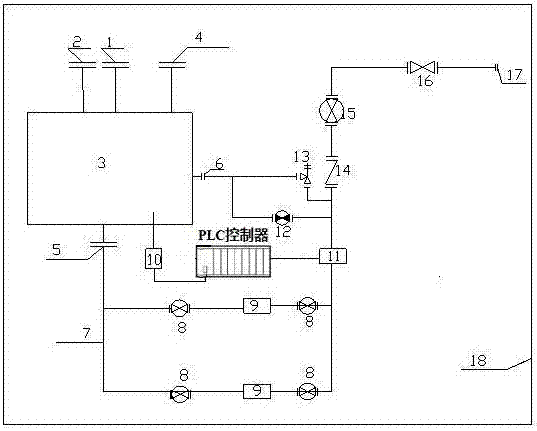
[0021] This embodiment provides a skid-mounted automatic liquid discharge device for emptying and liquid separation, including a gas-liquid separator 3, a skid seat 18 is provided below the gas-liquid separator 3, and a bottom of the gas-liquid separator 3 The sewage outlet 5 is connected with the reciprocating pump 11 located on the skid base 18 through the sewage pipeline 7, and the gas-liquid separator 3 is provided with a liquid level monitor 10, and the liquid level monitor 10 is connected with the skid base 18. The input end of the PLC controller is connected, and the reciprocating pump 11 is connected with the output end of the PLC controller.

[0022] Working process: When the gas gathering station is put into operation, the incoming gas from the vent pipeline enters the gas-liquid separator 3 through the incoming gas interface 1, the incoming liquid from the sewage pipe enters the gas-liquid separator 3 through the incoming liquid interface 2, and the incoming gas from...

Embodiment 2

[0026] On the basis of Embodiment 1, a first ball valve 8 and a filter 9 are sequentially provided between the sewage pipeline 7 and the reciprocating pump 11. In this embodiment, after the sewage comes out through the sewage outlet 5, it enters the sewage pipeline 7 and passes through the first ball valve. 8 and a filter 9, wherein the filter 9 filters solid particles and impurities in the liquid, and then enters the reciprocating pump 11 for pressurization.

Embodiment 3

[0028] On the basis of Embodiment 1, a check valve 14 is provided on the outlet pipeline of the reciprocating pump 11; the middle and lower part of the gas-liquid separator 3 is provided with a liquid return port 6, and the liquid return port 6 is connected to the reciprocating pump 11 through the first pipeline. A safety valve 13 is provided on the first pipeline, and a second pipeline is provided between the liquid return port 6 and the outlet pipeline of the reciprocating pump 11, and a second ball valve 12 is provided on the second pipeline.

[0029] When the reciprocating pump 11 is turned on for the first time, the check valve 14 is closed and the second ball valve 12 is opened. After the sewage comes out through the sewage outlet 5, it enters the sewage pipeline 7, and then enters the reciprocating pump 11 for pressurization. After pressurization, the sewage passes through the second ball valve 12, and the liquid return port 6 enters the gas-liquid separator 3 for separ...


PUM


Abstract

The invention belongs to the technical field of venting and liquid separation in oil and gas fields, and specifically relates to a skid-mounted automatic liquid discharge device for venting and liquid separation, including a gas-liquid separator. The sewage outlet at the bottom of the device is connected to the reciprocating pump on the skid base through the sewage pipeline. The gas-liquid separator is equipped with a liquid level monitor, and the liquid level monitor is connected to the input end of the PLC controller on the skid base. connected, the reciprocating pump is connected to the output end of the PLC controller. The invention can realize gas-liquid separation of natural gas, automatic liquid drainage, pressurized water delivery, prevent the occurrence of slug flow, complete separation, and solve the problem that the natural gas passes through the drainage pipeline to the sewage tank, which may cause the sewage tank to be under pressure and cause rupture; it is convenient to skid Loading and transporting, while reducing labor intensity and improving work efficiency.

Description

technical field [0001] The invention belongs to the technical field of venting and liquid separation in oil and gas fields, and in particular relates to a skid-mounted automatic liquid discharge device for venting and liquid separation. Background technique [0002] Some liquid separation devices with gas-liquid separation function are widely used in oil and natural gas gathering and transportation production, as well as in oil, petrochemical, and combustible gas processing, to effectively separate impurities such as condensate oil, water, and solid particles. Reduce environmental pollution and ensure the safety of the plant and operators. [0003] At present, the separation device installed in the gas gathering station can only perform gas-liquid separation, and the drain valve needs to be manually opened or closed. The discharged liquid is discharged into the sewage tank, and then transported to the sewage treatment plant by sewage truck. With the production of the well si...

Claims


Application Information

Patent Timeline
Patent Type & Authority Patents(China)
IPC IPC(8): F17D3/14
Inventor 胡涛杨光胡建国郑欣王红霞薛岗范君来刘明堃王敏胡凤材
Owner XIAN CHANGQING TECH ENG
Why Eureka
Try Eureka