A cooling system for an electrical cabinet in a power distribution room

A technology of heat dissipation system and electrical cabinet, applied in the electrical field, can solve the problems of uneconomical, high energy consumption, easy damage to components, etc., and achieve the effect of good convection effect, good cooling efficiency, and not easy to rise.

Inactive Publication Date: 2017-02-08
STATE GRID SHANDONG ELECTRIC POWER +1
View PDF8 Cites 2 Cited by
  • Summary
  • Abstract
  • Description
  • Claims
  • Application Information

AI Technical Summary

Problems solved by technology

[0006] 1. Adopt the scheme of installing a fan in the electrical cabinet. Since the fan will vibrate when it is working, this vibration will be transmitted directly to the electrical components inside it through the cabinet body. When various electrical components are in a vibrating state for a long time, their internal The components are easily damaged, which affects the service life. On the other hand, various connecting lines and contacts are also disengaged due to long-term vibration, causing the entire system to fail. Therefore, there are problems in the scheme of using an internal fan;
[0007] 2. The electrical cabinet is generally placed in the electrical control room. If the electrical control room is not equipped with an air conditioner, the temperature of the entire electrical control room will be very high, especially in summer, due to the high temperature of the external air, the fan in the electrical cabinet has to work for a long time; In addition, if an air conditioner is installed in the electrical control room, most of the cold air generated by the air conditioner is building energy consumption, that is, the air in the entire electrical control room needs to be cooled, so the energy consumption will be high, which is not cost-effective;
[0008] 3. The control core in the electrical cabinet: the controller does not have a separate heat dissipation structure. Once the controller fails due to untimely heat dissipation, it will paralyze the entire system and cause immeasurable losses
[0009] Because there are above-mentioned technical problems in prior art, affect use, therefore must improve
[0010] The company has developed an electrical cabinet and its heat dissipation control method (application number 2015102008568), which is beneficial to the air duct located on the top of the power distribution room to dissipate heat, but the air duct is complicated to make, the volume is small, and the convection effect is poor, so the company made another further improvements

Method used


Image

  • A cooling system for an electrical cabinet in a power distribution room
  • A cooling system for an electrical cabinet in a power distribution room
  • A cooling system for an electrical cabinet in a power distribution room

Examples


Embodiment 1

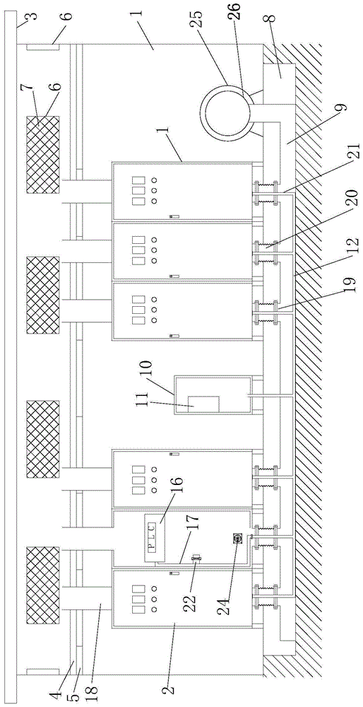
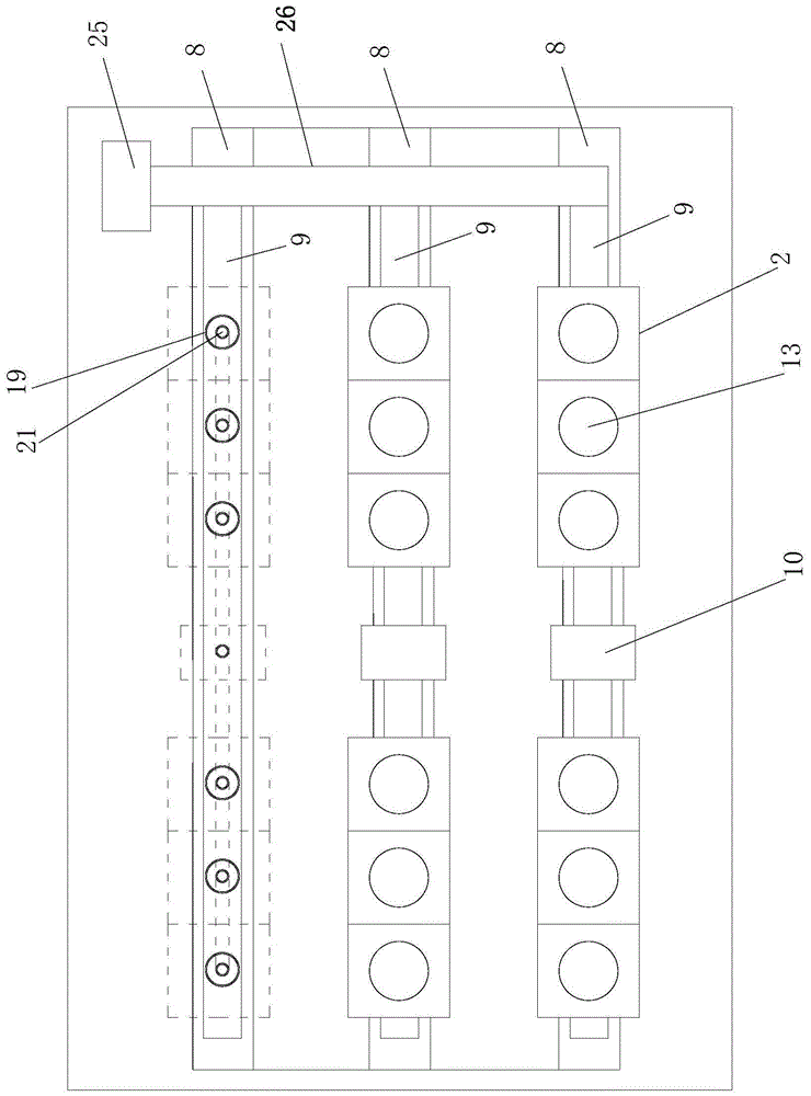
[0033] like figure 1 , 2As shown in . , the upper part of the power distribution room 1 is provided with a keel 4, and the lower part of the keel 4 is connected with a ceiling board 5, and all the ceiling boards 5 divide the power distribution room 1 into upper and lower spaces, and the power distribution room 1 is located on the ceiling board 5 Ventilation windows 6 are opened on all four sides of the upper part, and insect-proof nets 7 are arranged on the ventilation windows 6. A plurality of parallel slots 8 are opened on the ground of the power distribution room 1, and each slot 8 is provided with a ventilation window. Road 9; an air-conditioning cabinet 10 is provided at the upper center of each slot 8, and an air-conditioning 11 is provided in the air-conditioning cabinet 10, and electrical cabinets 2 arranged in a line are arranged on both sides of the air-conditioning cabinet 10, The width of the groove 8 is smaller than the air-conditioning cabinet 10 and the electr...

Embodiment 2

[0037] like Figure 4 , 5 As shown, the heat dissipation system of the electrical cabinet in the power distribution room described in this embodiment is different from Embodiment 1 in that the upper part of the exhaust pipe 18 is fixed on the keel 4, and the middle part of the exhaust pipe 18 is provided with A section of telescopic pipe 28 is provided with a flange 27 at the bottom of the exhaust pipe 18, and the flange 27 is connected with the electrical cabinet 2. The telescopic pipe 28 can be a plastic corrugated pipe, so that the exhaust pipe 18 can be stretched, and it is convenient to connect with the electrical cabinet 2 during installation.

Embodiment 3

[0039] like Image 6 As shown, the heat dissipation system of the electrical cabinet in the power distribution room described in this embodiment is based on Embodiment 1. A temperature sensor 29 is provided in each electrical cabinet 2, and a temperature sensor 29 is provided in one of the air-conditioning cabinets 10. The total controller 30, the temperature sensor 29 in each electric cabinet 2 measures the temperature tt in the electric cabinet 2 and inputs it to the total controller 30, and the total controller 30 controls the fan 25 and each electric cabinet The air outlet valve 23 and the fan 24 in 2 work and the control method is as follows:

[0040] i. the total controller 30 controls the blower fan 25 to work once every other period of time and lasts T; T can generally be selected as 3 to 5 minutes, and the interval time can be selected as 1-2 hours; the effect of this step is that the blower fan 25 can work regularly, remove the heat in all electrical cabinets 2 in t...


PUM


Abstract

The invention discloses a heat radiation system of electrical cabinets in a power distribution room. The heat radiation system comprises the power distribution room and the plurality of electrical cabinets in the power distribution room, wherein a rainproof roof is arranged on the top of the power distribution room; keels are arranged at the upper part of the power distribution room; suspended ceiling plates are connected below the keels; the power distribution room is divided into an upper space and a lower space by the suspended ceiling plates; an air-conditioning chamber is further formed in each electrical cabinet; the air-conditioning chambers are communicated with a connecting tube; an exhaust tube is correspondingly arranged above each electrical cabinet; the exhaust tubes penetrate through the suspended ceiling plates above the electrical cabinets so that the top parts of the exhaust tubes are positioned inside the upper space of the power distribution room; the bottom parts of the exhaust tubes are communicated with upper openings of corresponding electrical cabinets; a fan is further arranged on the ground of the power distribution room; the outlet tube of the fan is communicated with a blowing tube; the blowing tube is communicated with all air flues. As a plurality of heat radiation schemes are simultaneously implemented, the heat radiation effect is good, and normal operation of electrical elements inside the electrical cabinets of the power distribution room can be effectively ensured.

Description

technical field [0001] The invention relates to the electrical field, in particular to a cooling system for an electrical cabinet in a power distribution room. Background technique [0002] The electrical cabinet is a commonly used electrical product. The electrical cabinet is made of steel to protect the normal operation of the components. The materials for making electrical cabinets are generally divided into two types: hot-rolled steel plates and cold-rolled steel plates. Compared with hot-rolled steel sheets, cold-rolled steel sheets are softer and more suitable for the production of electrical cabinets. Electrical cabinets are widely used mainly in chemical industry, environmental protection industry, power system, metallurgical system, industry, nuclear power industry, fire safety monitoring, transportation industry and so on. [0003] During the use of the electrical cabinet, the internal electrical components will generate heat, which will increase the temperature ...

Claims


Application Information

Patent Timeline
Patent Type & Authority Patents(China)
IPC IPC(8): H02B1/56H02B1/28H02B1/24G05D23/19
CPCH02B1/28H02B1/565
Inventor 李松徐伟尹文杰李国成苏海勇张华珍张沈阳邓堃孙凯刘新鑫刘立阳孙奉杰王春勇潘富杰王岩徐晓涛姜凯郑朝谢志平孙宇斌王利王肖亚毕凯董博超杨伟王超王所钺
Owner STATE GRID SHANDONG ELECTRIC POWER
Why Eureka
Try Eureka