Novel edge grinding wheel and manufacturing method thereof
A technology for edging wheels and grinding wheels, which is applied in the direction of grinding/polishing equipment, abrasive materials, grinding devices, etc., which can solve problems such as difficulty in replacement, hidden dangers of production safety, and reduced service life of grinding wheels, so as to reduce production costs and have a long service life , the effect of reducing difficulty
- Summary
- Abstract
- Description
- Claims
- Application Information
AI Technical Summary
Problems solved by technology
Method used
Image
Examples
Embodiment 1
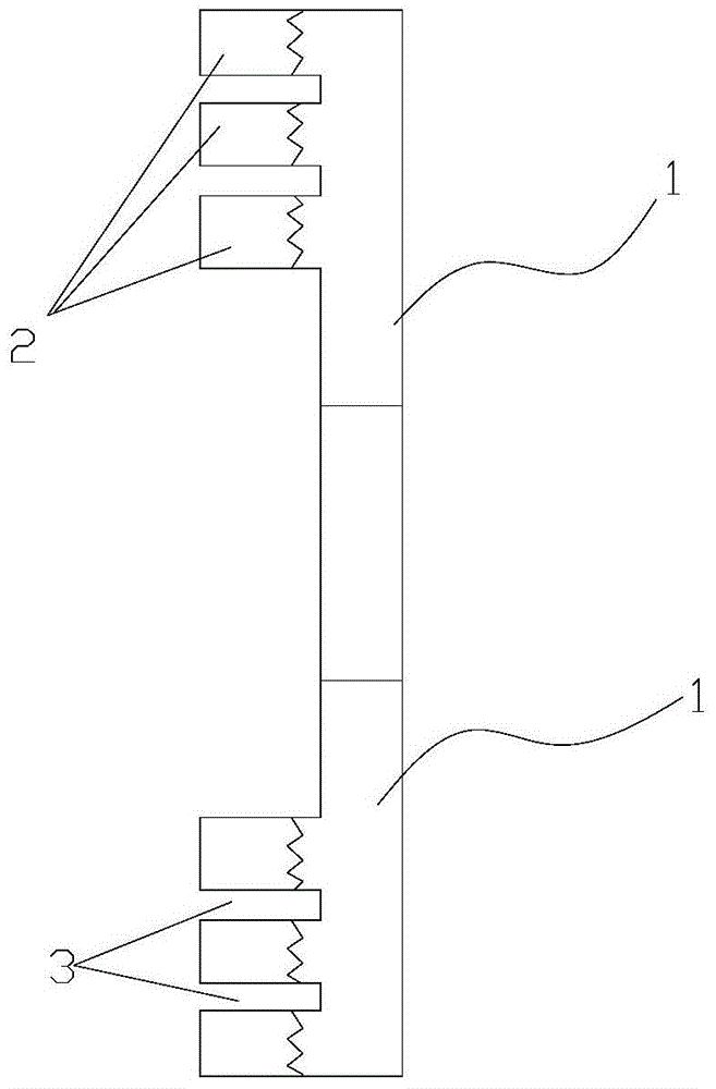
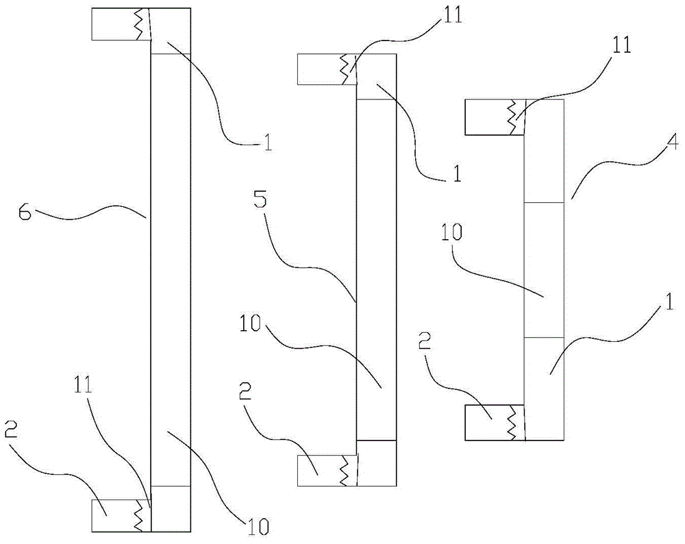
[0028] A new type of edging wheel, the edging wheel includes 3 concentrically distributed grinding wheels, the inner grinding wheel 4, the middle grinding wheel 5 and the outer grinding wheel 6 from the inside to the outside; The ring-shaped grinding layer 2 on the substrate, among the three grinding wheels (i.e. inner grinding wheel, middle grinding wheel and outer grinding wheel), an annular water seal groove 3 is arranged between any adjacent two ring-shaped grinding layers; The grinding wheel substrates of any two adjacent grinding wheels in the grinding wheel are fixedly connected; the three grinding wheel substrates include a joint 11 compounded with the annular grinding layer, and an annular substrate 10 integrated with the joint; the annular base 10 of the outer grinding wheel The height of the grinding layer is 10mm and the width is 9mm; the height of the grinding wheel base of the outer grinding wheel is 10mm, the inner diameter of the annular substrate on the grindin...
Embodiment 2
[0038] A new type of edging wheel, the grinding layer of the outer grinding wheel is made of the following components in parts by weight: 195 parts of 310-330 mesh copper powder, 105 parts of ultrafine iron powder with a particle size of 1-30 μm, 145 parts 32 parts of carbon powder of -155 mesh, 40 parts of diamond of 70-80 mesh, 48 parts of tin powder, 21 parts of zinc powder, 28 parts of silicon carbide of 750-850 mesh and 3 parts of liquid paraffin;
[0039] The grinding layer of the middle grinding wheel is made of the following components in parts by weight: 175 parts of 310-330 mesh copper powder, 78 parts of ultrafine iron powder with a particle size of 1-30 μm, and 30 parts of 145-155 mesh carbon powder , 26 parts of 100-120 mesh diamond, 23 parts of tin powder, 23 parts of zinc powder, 18 parts of 750-850 mesh silicon carbide and 2 parts of liquid paraffin;
[0040] The grinding layer of the inner grinding wheel is made of the following components in parts by weight: ...
Embodiment 3
[0042] A new type of edging wheel, the grinding layer of the outer grinding wheel is made of the following components in parts by weight: 205 parts of 310-330 mesh copper powder, 95 parts of ultrafine iron powder with a particle size of 1-30 μm, 145 parts 32 parts of carbon powder of -155 mesh, 36 parts of diamond of 70-80 mesh, 52 parts of tin powder, 19 parts of zinc powder, 32 parts of silicon carbide of 750-850 mesh and 2 parts of liquid paraffin;
[0043] The grinding layer of the middle grinding wheel is made of the following components in parts by weight: 185 parts of 310-330 mesh copper powder, 82 parts of ultrafine iron powder with a particle size of 1-30 μm, and 34 parts of 145-115 mesh carbon powder , 30 parts of 100-120 mesh diamond, 27 parts of tin powder, 27 parts of zinc powder, 22 parts of 750-850 mesh silicon carbide and 3 parts of liquid paraffin;
[0044] The grinding layer of the inner grinding wheel is made of the following components in parts by weight: 1...
PUM
| Property | Measurement | Unit |
|---|---|---|
| width | aaaaa | aaaaa |
| particle diameter | aaaaa | aaaaa |
| particle diameter | aaaaa | aaaaa |
Abstract
Description
Claims
Application Information
 - R&D
- Intellectual Property
- Life Sciences
- Materials
- Tech Scout
- Unparalleled Data Quality
- Higher Quality Content
- 60% Fewer Hallucinations
Browse by: Latest US Patents, China's latest patents, Technical Efficacy Thesaurus, Application Domain, Technology Topic, Popular Technical Reports.
© 2025 PatSnap. All rights reserved.Legal|Privacy policy|Modern Slavery Act Transparency Statement|Sitemap|About US| Contact US: help@patsnap.com


