Efficient pulse biological reaction device

A biological reaction device and pulse technology, which is applied in the field of high-efficiency pulse biological reaction devices, can solve the problems of high energy consumption in sludge digestion tanks, poor digestion effect of residual sludge, high operating costs, etc., and increase the gas production rate per unit of sludge , increase volume gas production, and reduce site occupancy

Active Publication Date: 2015-07-29
河北通持水务科技有限公司
View PDF7 Cites 8 Cited by
  • Summary
  • Abstract
  • Description
  • Claims
  • Application Information

AI Technical Summary

Problems solved by technology

[0005] The purpose of the present invention is to provide a high-efficiency pulse bioreactor to solve the problems of high e...

Method used


Image

  • Efficient pulse biological reaction device
  • Efficient pulse biological reaction device
  • Efficient pulse biological reaction device

Examples


Embodiment 1

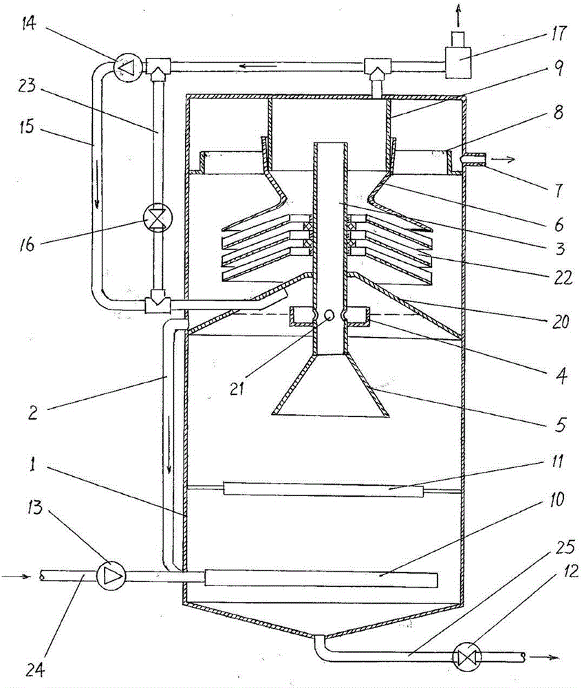
[0046] Embodiment 1: Anaerobic pulse bioreactor.

[0047] Such as figure 1 As shown, the high-efficiency pulse bioreactor of the present invention includes a closed tank body 1, which can be cylindrical, egg-shaped or square column-shaped, and the diameter-to-height ratio of the tank body can be between 0.5-8. In the middle of the tank body 1 is provided with a cone-shaped intermediate partition 20 with the conical top upward, which divides the inner cavity of the tank body 1 into an upper cavity and a lower cavity, and a connecting link is connected and fixed at the central cone top of the intermediate partition 20 . The air lift tubes 3 in the upper and lower chambers, the air lift tubes 3 can be round tubes, square tubes, elliptical tubes or polygonal tubes. On the outer wall of the airlift pipe 3 in the tank body lower cavity, a water blocking plate 4 is connected, and the water blocking plate 4 has an upward opening, and its shape can be circular, square or its shape. T...

Embodiment 2

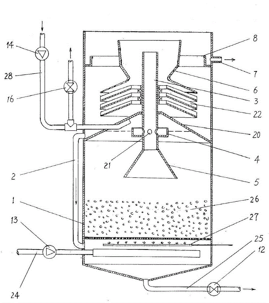
[0056] Example 2: Aerobic pulse bioreactor.

[0057] Such as image 3 As shown, the high-efficiency pulse bioreactor includes an open tank body 1, and a conical middle partition 20 is arranged in the middle of the tank body 1 to divide the tank cavity into an upper chamber and a lower chamber, and the middle partition 20 The center conical top of the center cone is pierced and fixed with the airlift tube 3 connected to the upper and lower chambers, and the lower port of the airlift pipe 9 is connected with an extension pipe extending to the lower chamber, and the lower port of the extension pipe is a straight cylinder mouth, a cone mouth or trumpet. A water blocking plate 4 is connected to the outer wall of the air lifting pipe 3 located in the lower cavity of the tank body, and an air hole 21 is opened on the air lifting pipe 3 in the water blocking plate.

[0058] A ventilation pipe 28 is plugged into the tank body 1, and the insertion end of the ventilation pipe 28 extend...


PUM

PropertyMeasurementUnit
Horizontal angleaaaaaaaaaa

Abstract

The invention relates to an efficient pulse biological reaction device. The efficient pulse biological reaction device is characterized in that a gas-collecting hood, a flow guide cylinder, an effluent weir, a precipitation plate, a middle spacing plate, a gas stripping pipe and a water blocking disk are arranged in a pot body, wherein a gas hole is formed in the gas stripping pipe, and the height of the gas hole does not exceed that of the side edge of the water blocking disk; an exhaust opening is formed in the top of the pot body surrounded by the gas-collecting hood, a gas return pipe is connected to the exhaust opening, and the gas return pipe is inserted to a tapered top region on the bottom surface of the middle spacing plate from the side part of the pot body; a flow guide grid and a water distributing device are arranged at the bottom of the pot body, the water distributing device is connected with a feed pipe on the outer side of the pot body; a return passage for transporting upper liquid back to the pot body through the bottom of the pot body is arranged at the upper part, corresponding to the outside edge of the middle spacing plate, of the pot body. The biological reaction device disclosed by the invention can generate gas stripping pulse automatically so as to have a good stirring function on sludge in the pot body, and creates a good uniform growing environment for the anaerobic reaction of microorganisms, so that the pulse biological reaction device disclosed by the invention keeps higher processing efficiency and has a higher gas-generating rate by using the sludge.

Description

technical field [0001] The invention relates to a sewage treatment device, in particular to a high-efficiency pulse biological reaction device. Background technique [0002] Anaerobic digestion of sludge refers to the process in which the biodegradable organic matter in the sludge is decomposed into methane, hydrogen and carbon dioxide by facultative bacteria and anaerobic bacteria under anaerobic conditions, so that the sludge is stabilized. This is one of the commonly used methods for sludge reduction and stabilization. The organic matter in the sludge is degraded by anaerobic microorganisms, and the organic matter is converted into methane, carbon dioxide, hydrogen, hydrogen sulfide and other substances. The advantage of sludge anaerobic digestion is that organic matter is digested to generate energy, which can be developed as potential energy for use as fuel and power. [0003] Mixing is one of the process conditions to improve the efficiency of sludge digestion. Adeq...

Claims


Application Information

Patent Timeline
IPC IPC(8): C02F3/00C02F3/28C02F3/12
CPCY02W10/10
Inventor 刘森池张灵芝王玮郭红陆佳乐李晖王建峰张建伟张晓强张桐海
Owner 河北通持水务科技有限公司
Why Eureka
Try Eureka